00191369-01.pdf - 第375页
User Manual HS-50 10 Component han dling Software-Version 5.0101/99 Issue 10.5 Used tape cutter 373 The used tape guide channels (see item 1 in Fig. 10.5 - 3) are lo cated upstre am of the feed er mod- ules. They ar e po…
10 Component handling User Manual HS-50
10.5 Used tape cutter Software-Version 5.01 01/99 Issue
372
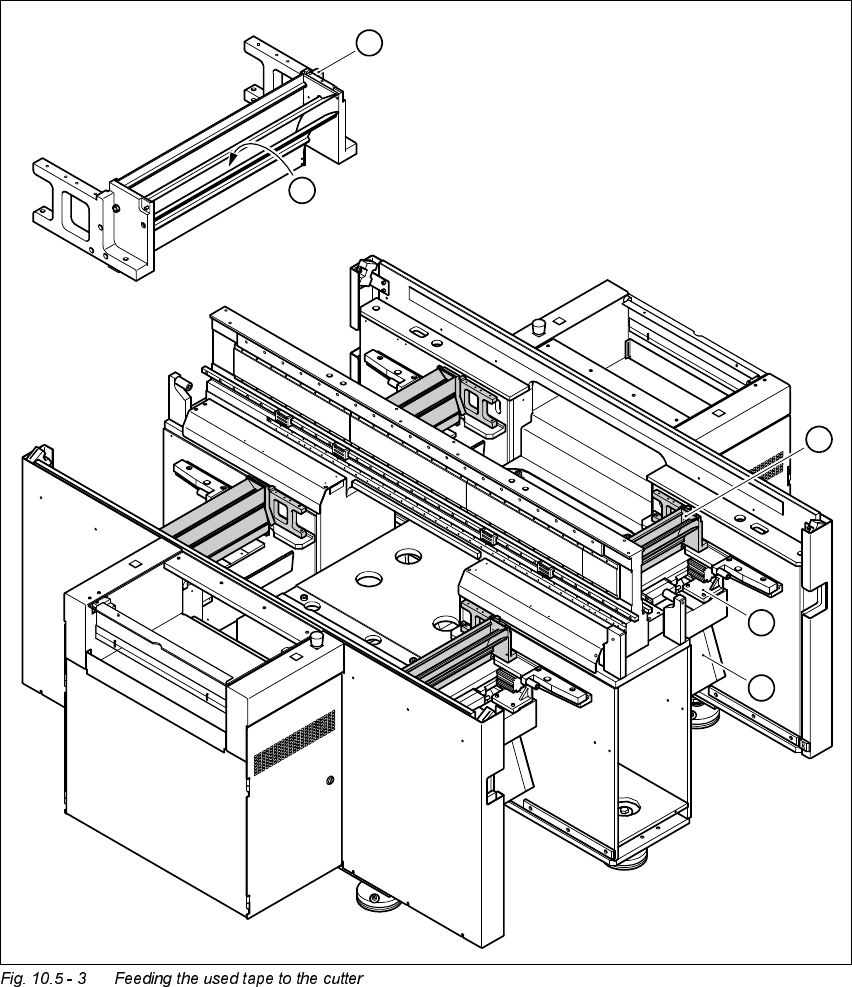
)HHGLQJWKHXVHG WDSHWRWKHFXWWHU
.H\ WR )LJ
(1) Used tape guide channel
(2) Channel for removal of the used tape
(3) Tape cutter
(4) Waste tape chute
1
2
1
3
4
User Manual HS-50 10 Component handling
Software-Version 5.0101/99 Issue 10.5 Used tape cutter
373
The used tape guide channels (see item 1 in Fig. 10.5 - 3) are located upstream of the feeder mod-
ules. They are positioned directly above the used tape cutters (see item 3 in Fig. 10.5 - 3).
The tape is automatically guided through the used tape guide channel into the used tape cutter
below. There, the tape is shredded by the pneumatically-actuated cutting blade. The waste tape
then passes via the waste tape chute (see item 4 in Fig. 10.5 - 3) into the component table’s waste
container.
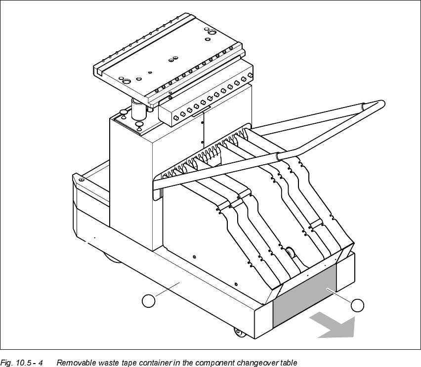
.H\WR )LJ
(1) Component changeover table
(2) Removable waste tape container
2
1
10 Component handling User Manual HS-50
10.6 Component changeover tables Software-Version 5.01 01/99 Issue
374
&RPSRQHQWFKDQJHRYHUWDEOHV
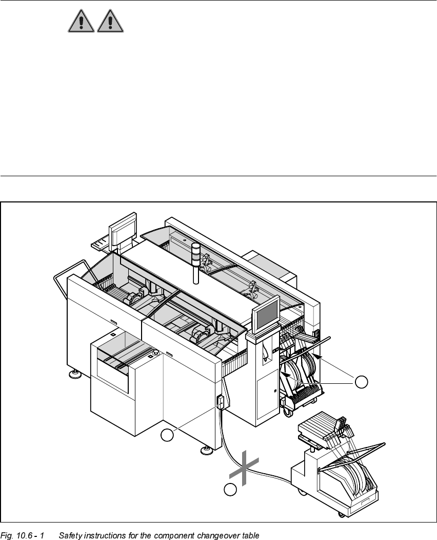
6DIHW\LQVWUXFWLRQV IRUGRFNLQJ DQGXQGRFNLQJWKHFRPSRQHQW FKDQJHRYHU
WDEOH
WARNING
Å Never reach into the gaps between the component changeover table and the placement sys-
tem frame while the machine is running (item 1 in Fig. 10.6 - 1).
Å Always check that the component changeover table is docked on the placement system before
connecting or disconnecting the power cable for the component changeover table at the socket
on the placement system (item 2 in Fig. 10.6 - 1).
Å NEVER connect the connecting cable for the component changeover table to the socket on the
placement system and then operate the component table outside the machine via the com-
pressed air control unit (item 3 in Fig. 10.6 - 1).
2
1
3