00191369-01.pdf - 第272页
6 Vision functions User Manual HS-50 6.6 Test Component Software-Version 5.01 Edition 01/99 270 The GF or package form fil e is store d in the lin e computer . Bas ically it consis ts of two main parts: – the geometri …
User Manual HS-50 6 Vision functions
Software-Version 5.01Edition 01/99 6.6 Test Component
269
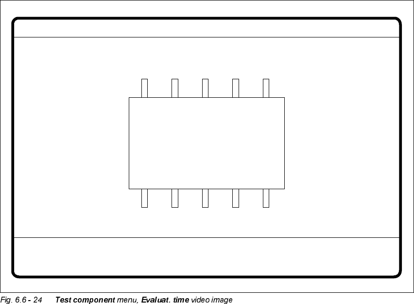
Å Press the RETURN key to start the measurement. Once the measuring procedure has ended,
the measuring time in msec is overlaid.
Å Press ESC to leave the option. The video image will disappear and the ‘Test component’ menu
will appear once more.
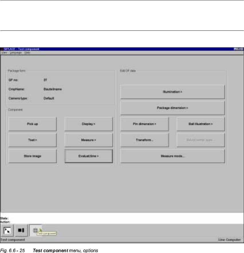
,QIRUPDWLRQRQWKH*URXSRI(GLW*)'DWD2SWLRQV
The following options belong to the (GLW*)GDWD group of options:
– Lighting
– Package dimensions
– Lead dimensions
– Ball illustration
– Transformation table
– Select component type (80F machines only)
– Measure mode
GF No. = 5
Evaluation time
Evaluation time [ms] =
RET: Measure component
6 Vision functions User Manual HS-50
6.6 Test Component Software-Version 5.01 Edition 01/99
270
The GF or package form file is stored in the line computer. Basically it consists of two main parts:
– the geometric package form data and
– the sensor-specific data.
The sensor-specific part contains
– the measurement conditions for the component,
– the type of lighting and
– the transformation table data.
NOTE
The buttons of the options of the 7HVWFRPSRQHQW menu will only be active if you have already
loaded a package form.

User Manual HS-50 6 Vision functions
Software-Version 5.01Edition 01/99 6.6 Test Component
271
This menu allows you to change
– the lead dimensions,
– the package dimensions,
– the ball imaging parameters,
– the illumination parameters and,
– the transformation table.
– Lead dimension parameters are
– optical lead length in the x and y directions of the component
– optically lead width in the x and y directions of the component
– pitch of the leads in the x and y directions of the component. Pitch means the distance from
the center of one lead to the center of the next.
– number of leads in the x and y directions of the component
NOTE
The pitch and number of leads can only be changed in the line computer.
– Package dimension parameters are
– the outside dimensions of the component in millimeters in the x and y directions. Outside
dimensions means the optical dimensions of the component including the lead dimensions.
The geometric dimensions of the leads and component are stored in the GF file in the line
computer. Depending on the geometry of the component and on its illumination by the com-
ponent camera, it is possible that imaging errors may occur. The image does not reproduce
the life-size geometric dimensions but reduces them. This is what is called imaging reduc-
tion. For this reason one refers to the optical dimensions of the leads and component. For
each lead dimension and package form the reduction factor is included in the GF file in the
line computer and can be modified with this menu. The reduction factor is entered in the
"Real-MA" file.
As regards defining the position of the origin of the coordinates system and defining regular and
irregular components, please refer to Section 6.3.2 on page 6 - 197.
– Ball imaging parameters are
– inner and outer radius type
– inner and outer radius
– contrast