00191369-01.pdf - 第40页
1 Introduction User Manual HS-50 1.12 Overview of the modules - gant ries Software Version 5.01 01/99 I ssue 38 6 WUXFWXUHRIWKH[D[LV The x axis essent ially cons ists of the following main modu les: – ga n…
User Manual HS-50 1 Introduction
Software Version 5.01 01/99 Issue 1.12 Overview of the modules - gantries
37
2YHUYLHZRIWKHPRGXOHVJDQWULHV
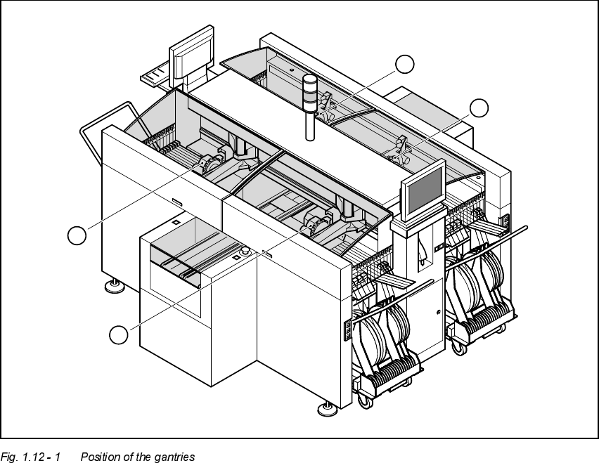
3RVLWLRQRIWKHJDQWULHV
1. Gantry 1 (sector 1)
2. Gantry 2 (sector 2)
3. Gantry 3 (sector 3)
4. Gantry 4 (sector 4)
The gantry system consists of two functional groups
–x axis
–y axis
4
1
2
3
1 Introduction User Manual HS-50
1.12 Overview of the modules - gantries Software Version 5.01 01/99 Issue
38
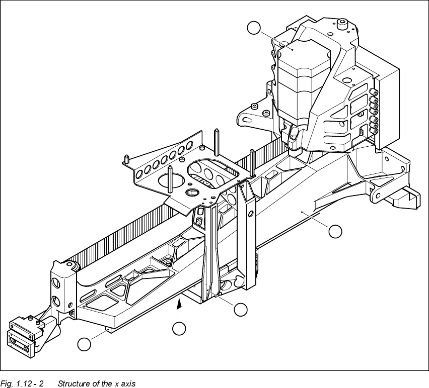
6WUXFWXUHRIWKH[D[LV
The x axis essentially consists of the following main modules:
– gantry arm (1)
– head mount (2)
– linear measuring system (3)
– x axis guide system (4)
– x axis three-phase AC servomotor (5)
The head mount holds the following components
– sub-gantry camera (camera for the PCB vision system)
– head board
– measuring head for the x axis measuring system
– revolver placement head
5
1
2
4
3
User Manual HS-50 1 Introduction
Software Version 5.01 01/99 Issue 1.12 Overview of the modules - gantries
39
7HFKQLFDOGDWDIRUWKH[D[LV
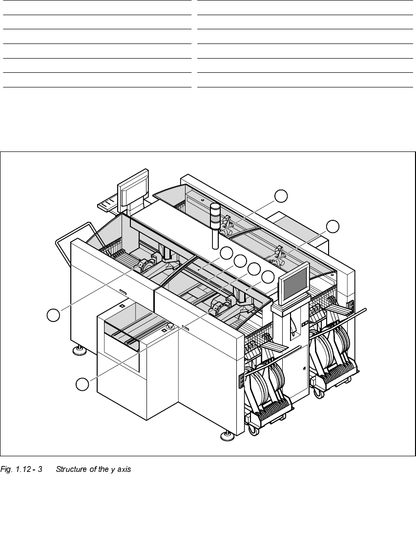
6WUXFWXUHRIWKH\D[LV
Drive Three-phase AC servomotor/toothed belt
Maximum speed 2.5 m/sec.
Traversing path 375 mm
Distance measuring system Metal linear scale
Measured length 400 mm
Scale length 420 mm
Resolution 1 µm
1. Gantry 1 5. Permanent magnet
2. Gantry 2 6. Guide system
3. Gantry 3 7. Measuring system
4. Gantry 4 8. Adapter plate
4
1
2
3
5
6
7
8