00197088-03_AI_Barcode_SICK620_SX12_X-S_TX_DE_EN.pdf - 第102页
3 Installation 3.8 Running and Connecting the Cable 102 Assembly Instructions / Montageanleitung SIPLACE TX-Series, X-Series S, SX1/SX2 V2 Option PCB Barcode / LP-Barcode (Lector 620) 05/2019 Removing the covers Fig.52:…
3 Installation
3.8 Running and Connecting the Cable
Assembly Instructions / Montageanleitung SIPLACE TX-Series, X-Series S, SX1/SX2 V2
Option PCB Barcode / LP-Barcode (Lector 620) 05/2019
101
3.8.2 SIPLACE X-Series S: Running and connecting cables
The connectors for the PCB barcode readers are located on the conveyor control units.
The conveyor control units are located under the lifting table plate of placement area1.
Removing the lifting table plate
The connectors for the PCB barcode readers are located under the lifting table plate.
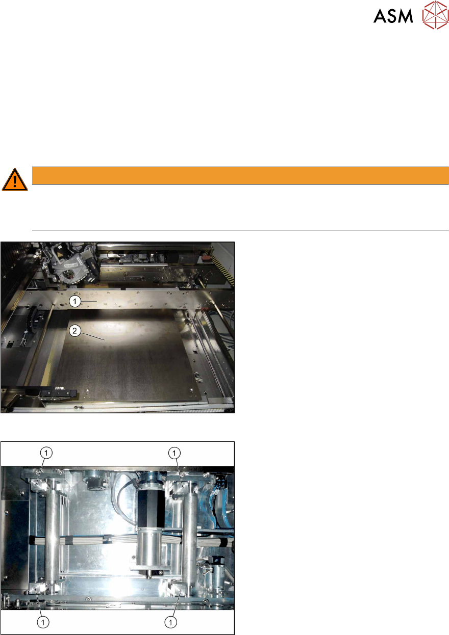
► Remove the lifting table plate in placement area 1, using the following procedure. (Remove
both lifting table plates for dual conveyors.)
WARNING
Heavy machine part
Take care when lifting out the plate.
► Wear safety shoes.
Fig.50: Dismantling the lifting table plate
► Move the conveyor sides(1) into a
position which allows you best access
for work.
► Loosen the screws (M6x30) fastening
the lifting table plate (2) and remove
the lifting table plate from the machine.
The lifting table plate is pinned to the
table plate guides but can be easily
pulled off.
Fig.51: Lifting table plate guides
► Mark the positions of the lifting table
plate guides (1) to make it easier to refit
them later on. Make sure you do not
confuse them. If you do, you will need
to reset the parallelism of the lifting
table plates after installation (see ser-
vice manual).
3 Installation
3.8 Running and Connecting the Cable
102 Assembly Instructions / Montageanleitung SIPLACE TX-Series, X-Series S, SX1/SX2 V2
Option PCB Barcode / LP-Barcode (Lector 620) 05/2019
Removing the covers
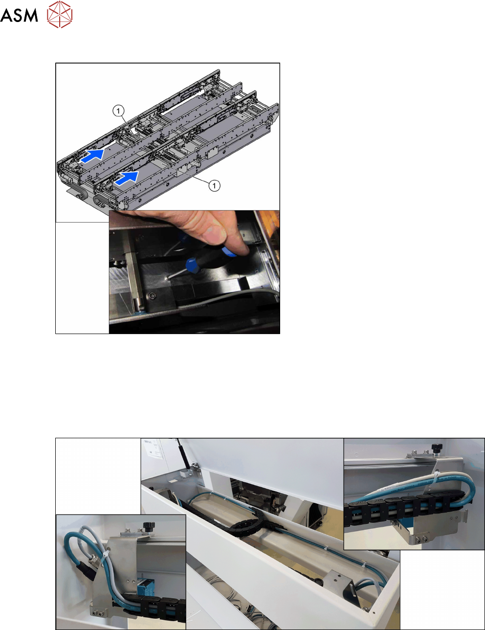
Fig.52: Removing the covers
► Loosen the screws of the covers(1) on
top of the conveyor control units in the
input area and remove the covers.
Cable routing
Assembly kits:
●
Electric mounting 2D PCB Barcode X-Series S SC [03104886-xx]
●
A dual conveyor requires "Electric mounting 2D Barcode X-Series S DC[00166666‑xx]" in ad-
dition
Fig.53: Overview of cable routing
3 Installation
3.8 Running and Connecting the Cable
Assembly Instructions / Montageanleitung SIPLACE TX-Series, X-Series S, SX1/SX2 V2
Option PCB Barcode / LP-Barcode (Lector 620) 05/2019
103
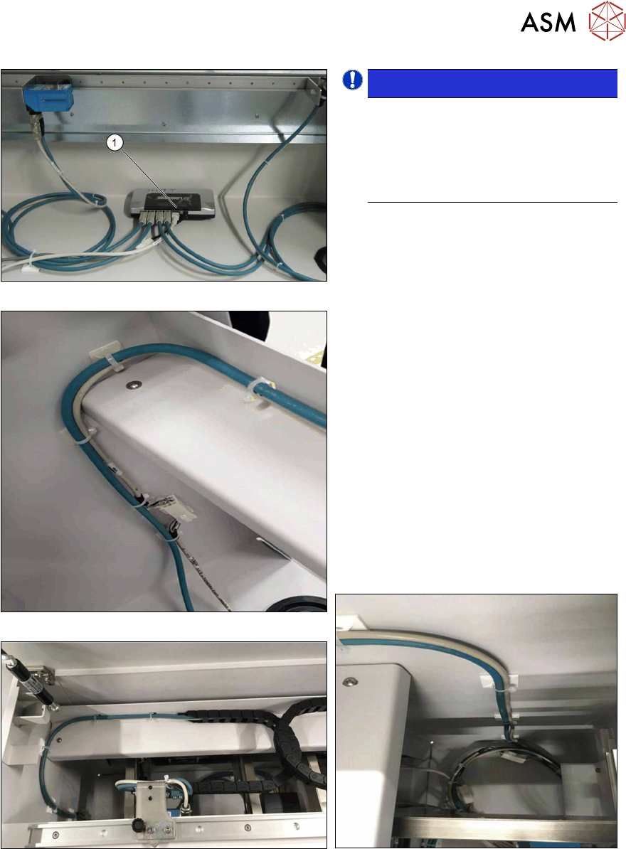
Fig.54: Switch cabling
Fig.55: Cable routing, on left
Fig.56: Cable routing, at top
NOTICE!
LAN cable
The LAN cable is only mandatory for
the configuration of the PCB barcode
scanner. For the operation and func-
tions of the PCB barcode scanners the
LAN cable is not absolutely necessary.
.
► Connect the LAN cable to the switch (1).
► Connect the power supply cable
(DC5V) [03104923‑xx] to the switch
and to the cable [03104892‑xx].
The cable [03104892‑xx] is among the
cables for the upper PCB barcode
reader.
► Make sure that the cables have enough
play. In contrast to the top PCB bar-
code readers, the cables for the bottom
PCB barcode readers are not run
through a trailing chain.
► Use the Klettostar fastener to fasten
the switch to the bottom of the input
conveyor extension.
► In case of unnecessary cable length,
place the cables at the bottom of the in-
put conveyor extension.
Fig.57: Cable routing, on right