00197088-03_AI_Barcode_SICK620_SX12_X-S_TX_DE_EN.pdf - 第124页
5 Appendix 5.3 Excerpts from the Service Manual 124 Assembly Instructions / Montageanleitung SIPLACE TX-Series, X-Series S, SX1/SX2 V2 Option PCB Barcode / LP-Barcode (Lector 620) 05/2019 5.3.1 Replacing the LAN card If …
5 Appendix
5.3 Excerpts from the Service Manual
Assembly Instructions / Montageanleitung SIPLACE TX-Series, X-Series S, SX1/SX2 V2
Option PCB Barcode / LP-Barcode (Lector 620) 05/2019
123
1. This fixed dividing line (corner):
This is used for pattern recognition and to calculate the rotary position of the data matrix code.
2. The unclosed border (opposite corner):
This open corner is used to identify the number of lines and columns. This is known as the
"matrix density“. On the ECC 200, the element in the top right-hand corner is white.
3. The storage area:
This contains the binary information in coded form. Depending on the cell size, it also defines
the number of possible items of information.
4. The "quiet zone":
This empty zone surrounds the data matrix code. It contains no information and is not used for
orientation. The width of the rest zone is one field or one line.
Advantages of data matrix code:
●
Flexible in terms of the range of applications
●
Very high information density in the smallest space (over 2000 characters)
●
Scanning is possible from any angle
●
Minimal requirements in terms of color contrast and print quality and thus suitable for direct
labelers (e.g. laser labelers or needle embossing) as these require less contrast than for bar-
codes. This means that less contrast is needed than for barcodes.
●
Error correction using the "Reed-Solomon" algorithm: up to 25 % of the code may be dam-
aged.
Sample applications:
●
Scanning permanent direct labels (e.g. on tools, motor components, drive parts, surgical in-
struments, etc).
●
Production / manufacturing (identification of electronic components, tools)
●
Chemical and biomedical analysis instruments
●
PCBs
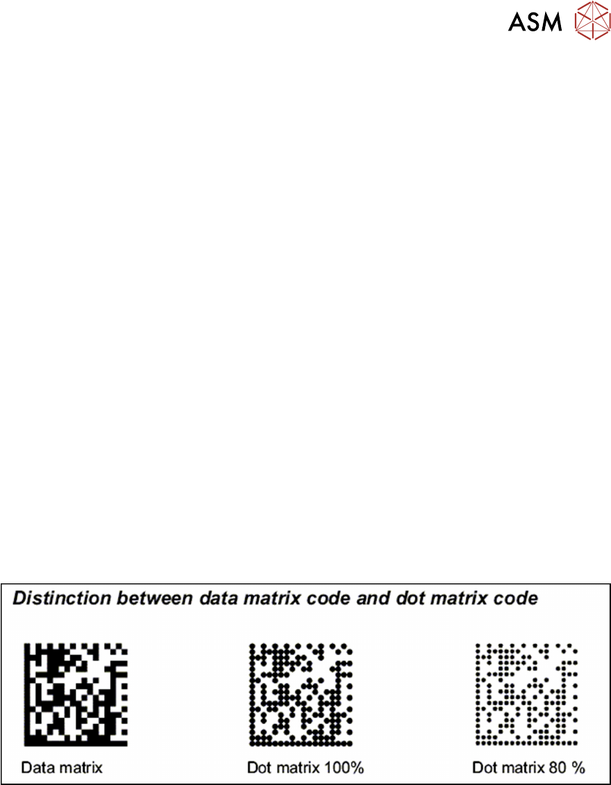
Fig.84: Data matrix - and DOT matrix barcodes
5.3 Excerpts from the Service Manual
The following chapters are excerpts from the service manual for your machine. If required, further
information is provided there.
●
Service Manual SIPLACE SX1/SX2 V2 [DE:00196999‑xx] [EN:00197000‑xx]
●
Service manual SIPLACE TX-Series V1 [DE:00198149‑xx] [EN:00198150‑xx]
●
Service manual SIPLACE TX-Series V2 [DE:00198538‑xx] [EN:00198539‑xx]
●
Service manual "SIPLACE X-Series S" [DE:00197041-xx] [EN:00197042‑xx]
5 Appendix
5.3 Excerpts from the Service Manual
124 Assembly Instructions / Montageanleitung SIPLACE TX-Series, X-Series S, SX1/SX2 V2
Option PCB Barcode / LP-Barcode (Lector 620) 05/2019
5.3.1 Replacing the LAN card
If a 3D Coplan or a barcode scanner is installed, the "LAN card PCI Gigabit SEMPRE
NC1000-1" [03112190-xx] is needed in addition.
This LAN card is used in the "BoxPC ABP402-A CPU1020E 2xPCI SSD (iBase)" [03120423-xx] in
machines from serial number Nxxxx onwards.
Parts, equipment and tools
●
LAN Card PCI Gigabit SEMPRE NC1000-1 [03112190-xx]
Overview
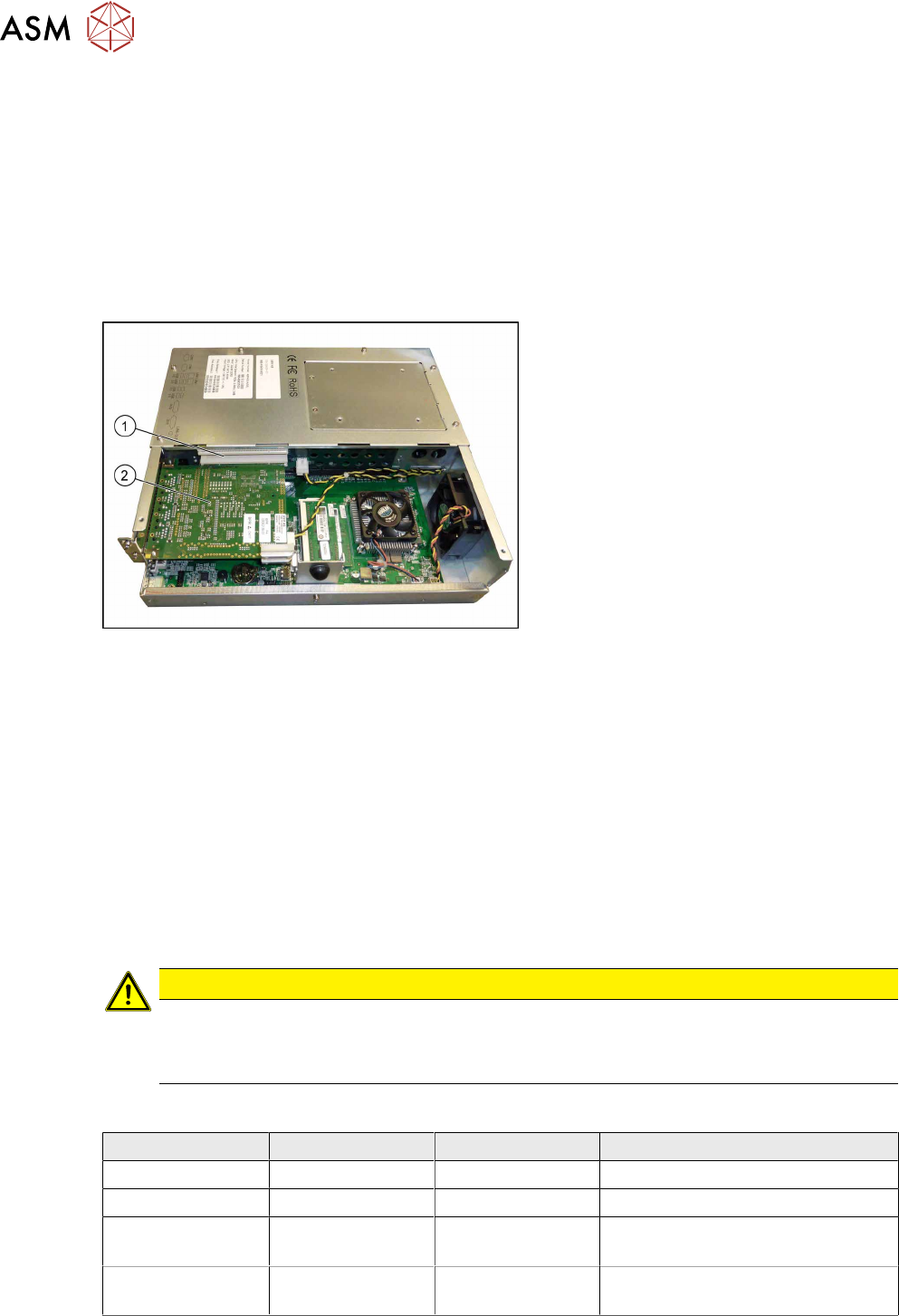
Fig.85: BoxPC ABP402-A CPU1020E 2xPCI SSD (iBase)
1. Free slot for the LAN card
2. Hotlink card
Removal
► Switch off the machine, disconnect it from the power supply and secure it to prevent
unauthorized reactivation.
1.2 "Preparatory work..." [}76]
► Dismantle and remove the BoxPC from the machine.
► Open the covers above the plug-in cards.
► Remove the screw fastening the LAN card and remove the LAN card.
Installation
► Follow the removal instructions in reverse order for installation. Also observe the following
instructions:
CAUTION
Installation instructions
► Make sure that the plug-in card is correctly fitted into its slot.
► Configure the IP settings for the LAN card (see below)
Overview of IP Addresses
IP address Subnet mask Comment
SIPLACE LAN 172.22.xxx.xxx 255.255.0.0 LAN connection on the computer
CIN box 192168255239 255255255224 LAN connection on the computer
Station computer 192168255249 255255255240 Additional LAN card for the
coplanarity computer
Coplanarity
computer
192168255253 255255255240
5 Appendix
5.3 Excerpts from the Service Manual
Assembly Instructions / Montageanleitung SIPLACE TX-Series, X-Series S, SX1/SX2 V2
Option PCB Barcode / LP-Barcode (Lector 620) 05/2019
125
5.3.2 Replacing the GigE Ethernet Adapter
Parts, equipment and tools
●
GigE ethernet adapter PCI-E I340-T4 [03105575‑xx]
●
GigE-Ethernet-Adapter PCI-E I350 T2 V2 BLK [03115569‑xx]
Overview
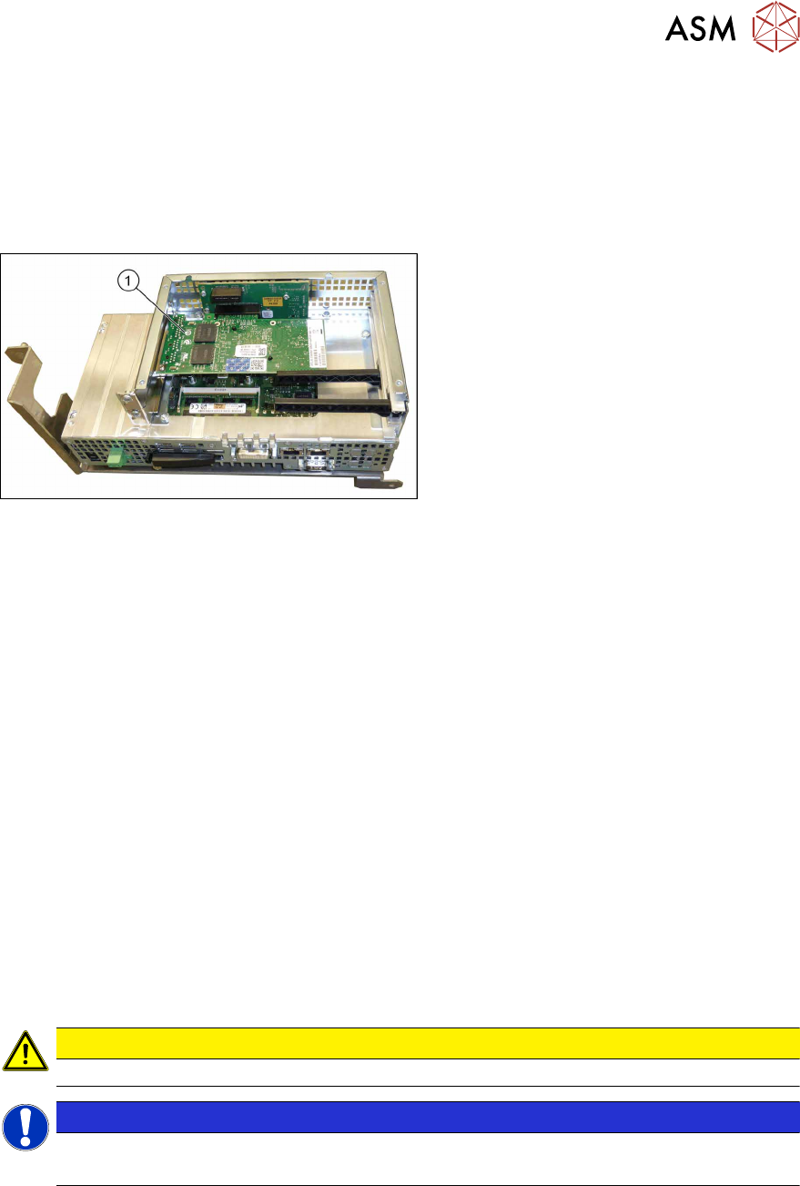
Fig.86: GigE Ethernet adapter in the BoxPC 427D
1. GigE ethernet adapter
Removal
► Switch off the machine, disconnect it from the power supply and secure it to prevent
unauthorized reactivation.
1.2 "Preparatory work..." [}76]
► Dismantle and remove the BoxPC from the machine.
► Remove the screws fastening the cover of the BoxPC and open the cover.
► Remove the screw fastening the Ethernet adapter and remove the Ethernet adapter.
Installation
► Follow the removal instructions in reverse order for installation. Also observe the following
instructions:
– Make sure that the plug-in card is correctly fitted into its slot.
5.3.3 Conveyor control TSP420 [03087642-xx]
Two TSP420 are fitted in SIPLACE TX-Series machines.
The conveyor control "TSP420 assembly" [03087642-xx] comprises the following components:
●
Main board: TSP420-M [ 03087640-xx ]
●
I/O board: TSP420-IO [ 03087641-xx ]
CAUTION
These two boards may not be separated!
NOTICE
Terminating resistor (cable set PCB dual conveyor [03110653‑xx])
The terminating resistor is set for the "Shuttle Option" by default.