00197088-03_AI_Barcode_SICK620_SX12_X-S_TX_DE_EN.pdf - 第75页
1 Introduction 1.1 Safety instructions Assembly Instructions / Montageanleitung SIPLACE TX-Series, X-Series S, SX1/SX2 V2 Option PCB Barcode / LP-Barcode (Lector 620) 05/2019 75 Fig.3: Power supply unit (SIPLACE TX -Ser…
1 Introduction
1.1 Safety instructions
74 Assembly Instructions / Montageanleitung SIPLACE TX-Series, X-Series S, SX1/SX2 V2
Option PCB Barcode / LP-Barcode (Lector 620) 05/2019
Machine switched off at the main switch, but still connected
DANGER
Risk of death by voltages!
Death, serious injury or considerable damage may result if these machines are handled
incorrectly.
The following components still carry potentially lethal voltages on the power supply even if
the main power switch is switched off:
► Main power supply cable connection terminals
► L1, L2, and L3 of the main switch S1
► Service socket X98 (if present)
► Testing terminals or points for checking the mains voltage
► The contactor safety breaker (CBS) still carries voltage for five minutes after switching
off at the main switch.
► The color of all individual wires which still carry potentially lethal voltages even if the
main power switch is switched off is orange.
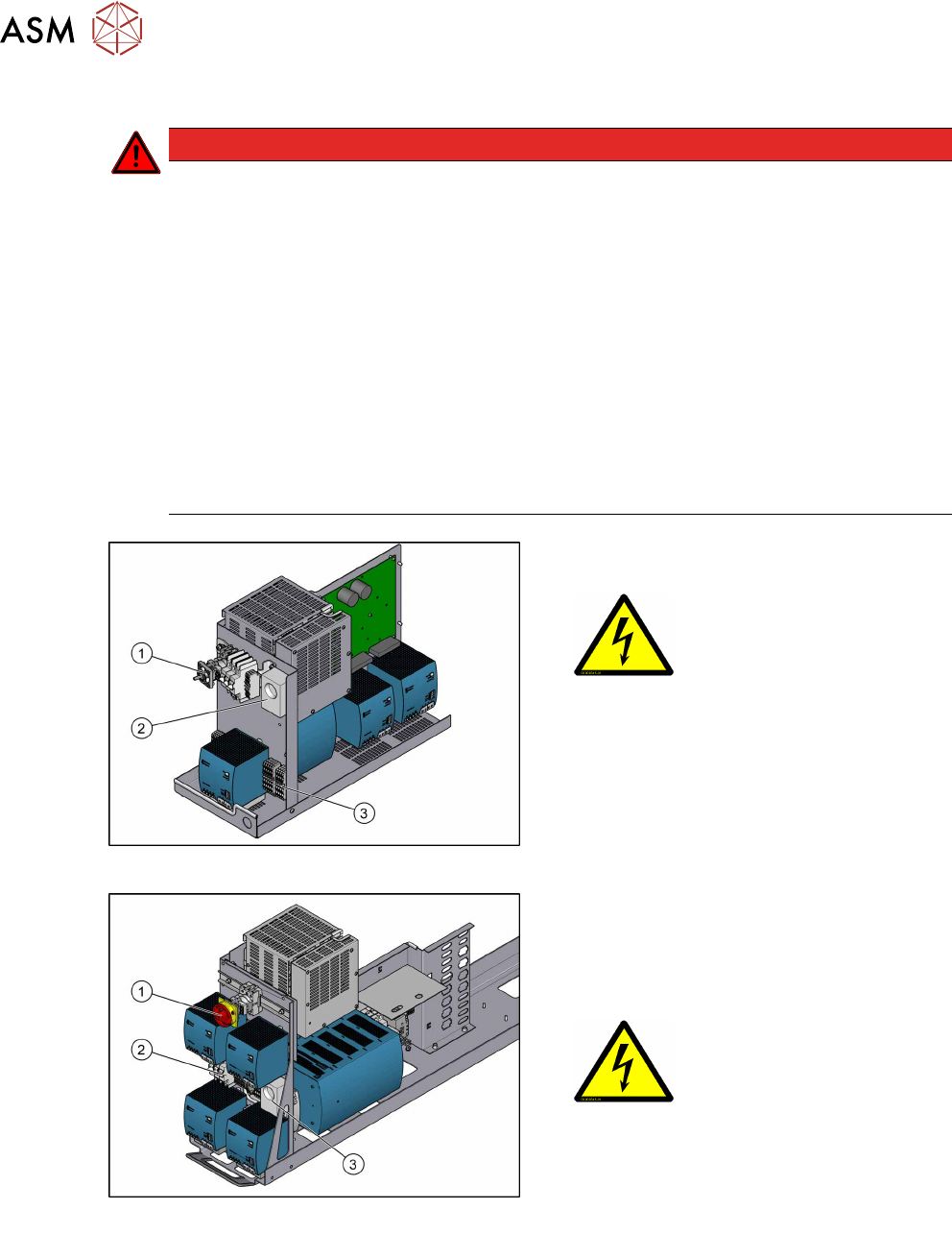
Fig.1: Power supply unit (SIPLACESX1/SX2, SMPS)
1. Main switch (S1)
2. Service socket (X98)
3. Main power supply cable connection ter-
minals (X94) for the power supply cable
Fig.2: Power supply unit (SIPLACE X-SeriesS, SMPS)
1. Main switch (S1)
2. Main power supply cable connection ter-
minals (X95) for the power supply cable
3. Service socket X98
(if present)
1 Introduction
1.1 Safety instructions
Assembly Instructions / Montageanleitung SIPLACE TX-Series, X-Series S, SX1/SX2 V2
Option PCB Barcode / LP-Barcode (Lector 620) 05/2019
75
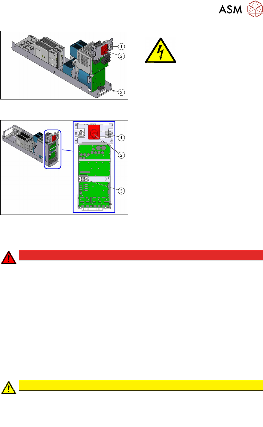
Fig.3: Power supply unit (SIPLACE TX -Series V1,
SMPS)
1. Service socket
2. Main Switch
3. Main power supply cable connection
Fig.4: Power supply unit (SIPLACE TX -Series V2,
SMPS)
1. Testing terminals for mains voltage
2. Main switch
3. Testing points for freedom from voltage
(160VDC/300VDC)
The connection for the power supply cable is
located in sector1.
Machine switched off at the main power switch and disconnected
DANGER
Hazardous voltages in the power supply unit!
The power supply unit houses components (capacitors) that can carry hazardous voltages
for about five minutes after the machine has been switched off and the power plug has
been unplugged.
► Wait at least five minutes before your start working on the power supply unit.
► Work on the power supply and the contactor safety breaker (CSB) must only be car-
ried out by service engineers of ASM Assembly Systems GmbH & Co. KG or by
machine owner service engineers who have been trained by ASM.
Compressed air conditions in the machine after switching off at the main switch
When the machine is switched off at the main power switch or if the power supply fails, the electric-
ally-controlled main valve of the compressed air unit closes. The pressure will drop to 0 MPa
(0bar) within five seconds.
1.1.5 Safety instructions for the gantry
CAUTION
Moving the gantry can damage the placement head.
When moving the gantry, observe the following:
► NEVER move the gantry by pushing with your hands against the placement head.
► NEVER push the gantry while the Z axis is lowered.
1 Introduction
1.2 Preparatory work...
76 Assembly Instructions / Montageanleitung SIPLACE TX-Series, X-Series S, SX1/SX2 V2
Option PCB Barcode / LP-Barcode (Lector 620) 05/2019
1.2 Preparatory work...
Purpose and scope
Before performing any preventive maintenance work, conversion work or service work, a procedure
of locking and tagging must be followed and warning signs must be attached if not stated other-
wise. If you do not need to switch off the machine, this will be clearly stated.
The procedure, when followed correctly, eliminates the possibility of an employee being injured.
NOTICE
Additional safety measures
This procedure represents the minimum lock out and tag out requirements for the machine
during preventive maintenance work and service work. Any additional safeguards needed
to complete work safely can be specified by facilities supervision, the safety officer, the
safety committee and the health department.
Description
Whenever it becomes necessary to isolate, control and release energy, the following procedure is
to be followed.
► Notify all affected employees.
► Switch off the machine and all additional devices. Carry out all normal stopping procedures:
ð Press the STOP button.
ð Shut down the station computer.
ð Switch off the machine using the main switch.
► Isolate the machine from all its energy sources:
ð Shut off the compressed air supply.
ð Shut off the main power supply.
► Lock out the machine.
ð Attach a lock wherever possible.
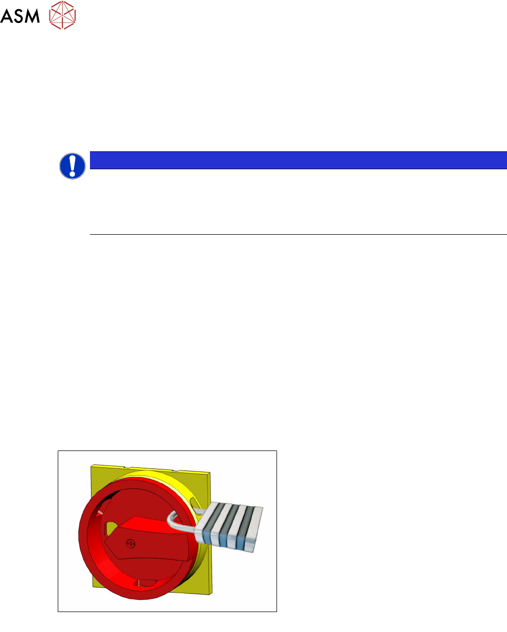
Fig.5: Attaching a padlock to the main power switch
Secure main switch
► Secure the main switch with a padlock.