00197088-03_AI_Barcode_SICK620_SX12_X-S_TX_DE_EN.pdf - 第98页
3 Installation 3.8 Running and Connecting the Cable 98 Assembly Instructions / Montageanleitung SIPLACE TX-Series, X-Series S, SX1/SX2 V2 Option PCB Barcode / LP-Barcode (Lector 620) 05/2019 Cable routing Assembly kits: …
3 Installation
3.7 Installing the LAN card in the BoxPC
Assembly Instructions / Montageanleitung SIPLACE TX-Series, X-Series S, SX1/SX2 V2
Option PCB Barcode / LP-Barcode (Lector 620) 05/2019
97
3.7 Installing the LAN card in the BoxPC
SIPLACE SX1/SX2 from serial no. Nxxxx
► Install the LAN card "LAN card PCI Gigabit SEMPRE NC1000-1" [03112190-xx] in the
"BoxPC ABP402-A CPU1020E 2xPCI SSD (iBase)" [03120423-xx].
For more information, see the service manual for your machine or read section 5.3.1 "Repla-
cing the LAN card" [}124] (identical procedure).
SIPLACE X-Series S up to serial no. Gxxxx:
► For these machines, no LAN card is required.
SIPLACE X-Series S from serial number Hxxxx onwards and
SIPLACE TX-Series:
► Install the LAN card "LAN card PCI Express 2x Gigabit LAN" [03118416‑xx] in the BoxPC
427D [03114177‑xx].
For more information, see the service manual for your machine or read section 5.3.2 "Repla-
cing the GigE Ethernet Adapter" [}125] (identical procedure).
3.8 Running and Connecting the Cable
SIPLACE SX1/SX2 from serial no. Nxxxx
► Continue with section 3.8.1 "SIPLACE SX1/SX2: Running and connecting the cable" [}97].
SIPLACE X-Series S:
► Continue with section 3.8.2 "SIPLACE X-Series S: Running and connecting cables" [}101].
SIPLACE TX-Series:
► Continue with section 3.8.3 "SIPLACE TX-Series: Running and connecting the cable" [}107].
3.8.1 SIPLACE SX1/SX2: Running and connecting the cable
The connectors for the PCB barcode readers are located on the conveyor control units.
The conveyor control units are located in the input area of the conveyor.
Removing the covers
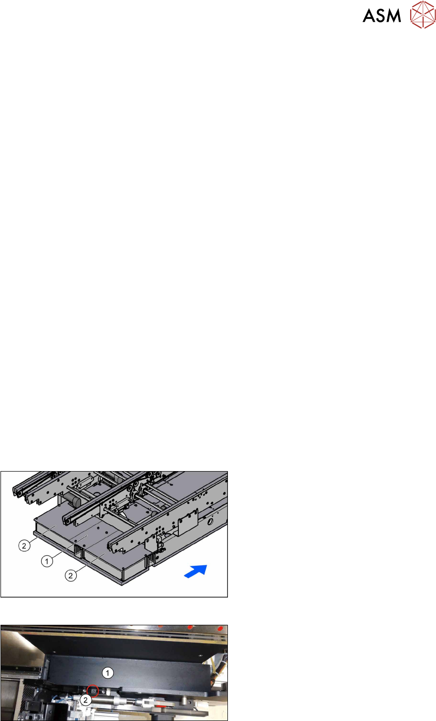
Fig.39: Removing the cover plates
► Undo the four screws fastening the
holding plate(1) and then remove the
holding plate.
► Remove the covers(2) on top of the
conveyor control units.
Fig.40: Cable duct cover
► Remove the screw(2) fastening the
cover(1) on top of the cable duct and
remove the cover.
3 Installation
3.8 Running and Connecting the Cable
98 Assembly Instructions / Montageanleitung SIPLACE TX-Series, X-Series S, SX1/SX2 V2
Option PCB Barcode / LP-Barcode (Lector 620) 05/2019
Cable routing
Assembly kits:
●
Electric mounting 2D PCB Barcode X-Series S SC [03104886-xx]
●
A dual conveyor requires "Electric mounting 2D Barcode X-Series S DC[00166666‑xx]" in ad-
dition
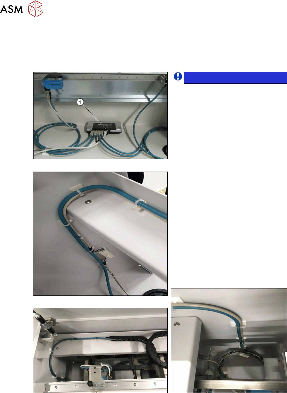
Fig.41: Switch cabling
Fig.42: Cable routing, on left
Fig.43: Cable routing, at top
NOTICE!
LAN cable
The LAN cable is only mandatory for
the configuration of the PCB barcode
scanner. For the operation and func-
tions of the PCB barcode scanners the
LAN cable is not absolutely necessary.
.
► Connect the LAN cable to the switch (1).
► Connect the power supply cable
(DC5V) [03104923‑xx] to the switch
and to the cable [03104892‑xx].
The cable [03104892‑xx] is among the
cables for the upper PCB barcode
reader.
► Make sure that the cables have enough
play. In contrast to the top PCB bar-
code readers, the cables for the bottom
PCB barcode readers are not run
through a trailing chain.
► Use the Klettostar fastener to fasten
the switch to the bottom of the input
conveyor extension.
► In case of unnecessary cable length,
place the cables at the bottom of the in-
put conveyor extension.
Fig.44: Cable routing, on right
3 Installation
3.8 Running and Connecting the Cable
Assembly Instructions / Montageanleitung SIPLACE TX-Series, X-Series S, SX1/SX2 V2
Option PCB Barcode / LP-Barcode (Lector 620) 05/2019
99
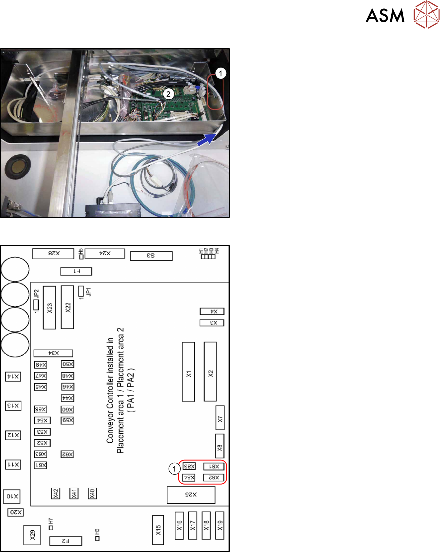
Fig.45: Routing the power supply cable
► Run the power supply cable through
the recess(1) to the conveyor con-
trol(2).
Fig.46: Conveyor control
1. Connectors for PCB barcode scanners
– Lane 1 / Single Conveyor:
PCB Barcode Scanner b 1 Lane
Bottom X81+83
PCB Barcode Scanner b 2 Lane
Top X82+84
– Lane 2 (Dual Conveyor only)
PCB Barcode Scanner b3 Lane Bot-
tom X81+83
PCB Barcode Scanner b4 Lane Top
X82+84
See also:
–
5.3.3 "Conveyor control TSP420
[03087642-xx]" [}125]
– 5.1 "Circuit Diagrams" [}113]
► Connect the cables to the connectors
X81 to X84(1).
► Repeat these steps for the second con-
veyor lane if required.