00197088-03_AI_Barcode_SICK620_SX12_X-S_TX_DE_EN.pdf - 第106页
3 Installation 3.8 Running and Connecting the Cable 106 Assembly Instructions / Montageanleitung SIPLACE TX-Series, X-Series S, SX1/SX2 V2 Option PCB Barcode / LP-Barcode (Lector 620) 05/2019 All other cables should be r…
3 Installation
3.8 Running and Connecting the Cable
Assembly Instructions / Montageanleitung SIPLACE TX-Series, X-Series S, SX1/SX2 V2
Option PCB Barcode / LP-Barcode (Lector 620) 05/2019
105
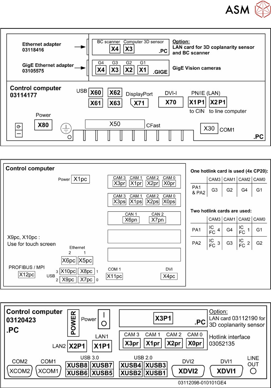
Fig.61: Overview of connections for BoxPC 427D
Fig.62: Overview of connections for BoxPC 627x/827x
Fig.63: Connections BoxPC ABP402-A CPU1020E 2xPCI SSD (iBase) [03120423-xx] (from Nxxxx onwards)
The BoxPC ABP402-A is fitted from approx. 2019 onwards.
3 Installation
3.8 Running and Connecting the Cable
106 Assembly Instructions / Montageanleitung SIPLACE TX-Series, X-Series S, SX1/SX2 V2
Option PCB Barcode / LP-Barcode (Lector 620) 05/2019
All other cables should be run to the con-
veyor control unit of the corresponding lane.
To do so, proceed as follows:
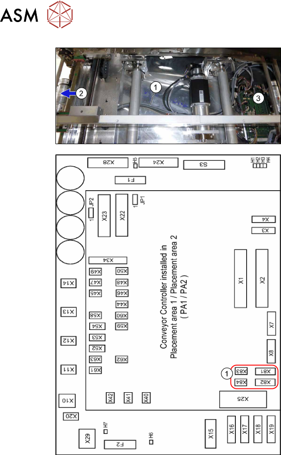
► Run the cables(1) from the input con-
veyor lane(2) to the conveyor con-
trol(3).
► Use cable ties to fix the cables to the
available cable bundles.
Fig.64: Conveyor control
1. Connectors for PCB barcode scanners
– Lane 1 / Single Conveyor:
PCB Barcode Scanner b 1 Lane
Bottom X81+83
PCB Barcode Scanner b 2 Lane
Top X82+84
– Lane 2 (Dual Conveyor only)
PCB Barcode Scanner b3 Lane Bot-
tom X81+83
PCB Barcode Scanner b4 Lane Top
X82+84
See also:
–
5.3.3 "Conveyor control TSP420
[03087642-xx]" [}125]
– 5.1 "Circuit Diagrams" [}113]
► Connect the cables to the connectors
X81 to X84(1).
► Repeat these steps for the second con-
veyor lane if required.
3 Installation
3.8 Running and Connecting the Cable
Assembly Instructions / Montageanleitung SIPLACE TX-Series, X-Series S, SX1/SX2 V2
Option PCB Barcode / LP-Barcode (Lector 620) 05/2019
107
3.8.3 SIPLACE TX-Series: Running and connecting the cable
The connectors for the PCB barcode readers are located on the conveyor control units.
The conveyor control units are located in the input area of the conveyor.
Removing the covers
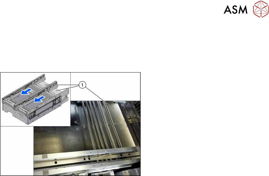
Fig.65: Removing the covers
► Remove the stay bolts fastening the
covers(1) and remove both covers.
Cable routing
Assembly kits:
●
Electric mounting 2D PCB Barcode X-Series S SC [03104886-xx]
●
Electric mounting 2D Barcode X-SeriesS DC [00166666‑xx]