00197088-03_AI_Barcode_SICK620_SX12_X-S_TX_DE_EN.pdf - 第109页
3 Installation 3.8 Running and Connecting the Cable Assembly Instructions / Montageanleitung SIPLACE TX-Series, X-Series S, SX1/SX2 V2 Option PCB Barcode / LP-Barcode (Lector 620) 05/2019 109 Fig.70: BoxPC-427D ► Run th…
3 Installation
3.8 Running and Connecting the Cable
108 Assembly Instructions / Montageanleitung SIPLACE TX-Series, X-Series S, SX1/SX2 V2
Option PCB Barcode / LP-Barcode (Lector 620) 05/2019
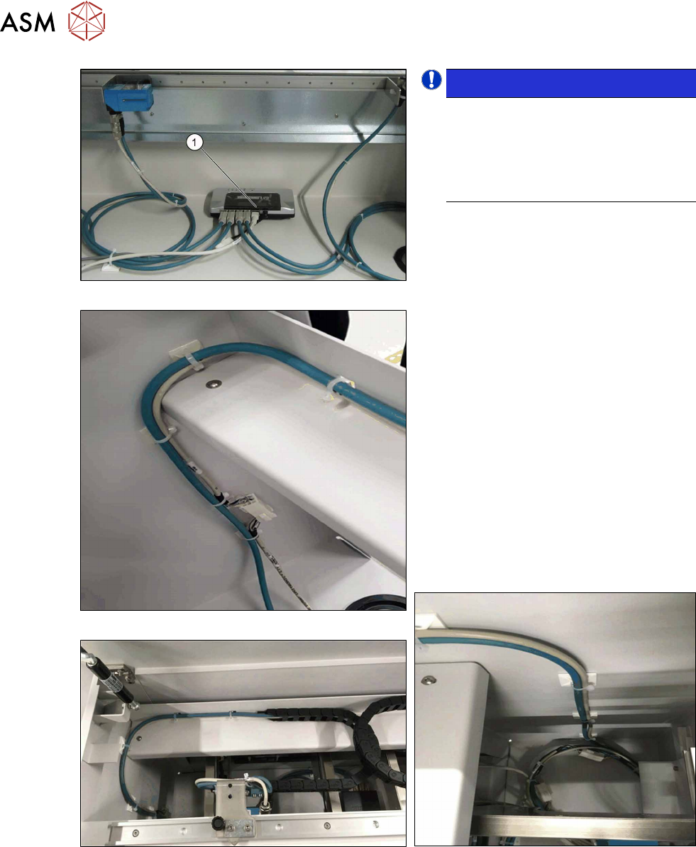
Fig.66: Switch cabling
Fig.67: Cable routing, on left
Fig.68: Cable routing, at top
NOTICE!
LAN cable
The LAN cable is only mandatory for
the configuration of the PCB barcode
scanner. For the operation and func-
tions of the PCB barcode scanners the
LAN cable is not absolutely necessary.
.
► Connect the LAN cable to the switch (1).
► Connect the power supply cable
(DC5V) [03104923‑xx] to the switch
and to the cable [03104892‑xx].
The cable [03104892‑xx] is among the
cables for the upper PCB barcode
reader.
► Make sure that the cables have enough
play. In contrast to the top PCB bar-
code readers, the cables for the bottom
PCB barcode readers are not run
through a trailing chain.
► Use the Klettostar fastener to fasten
the switch to the bottom of the input
conveyor extension.
► In case of unnecessary cable length,
place the cables at the bottom of the in-
put conveyor extension.
Fig.69: Cable routing, on right
3 Installation
3.8 Running and Connecting the Cable
Assembly Instructions / Montageanleitung SIPLACE TX-Series, X-Series S, SX1/SX2 V2
Option PCB Barcode / LP-Barcode (Lector 620) 05/2019
109
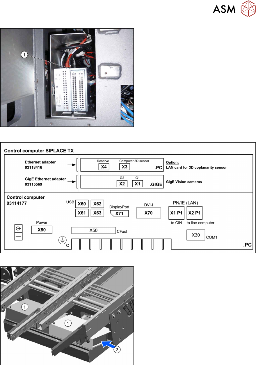
Fig.70: BoxPC-427D
► Run the LAN cable from the switch
through under the conveyor to the
BoxPC(1).
► Connect the LAN cable to the new LAN
card in the BoxPC
(see also 3.7 "Installing the LAN card in
the BoxPC" [}97]).
Fig.71: BoxPC 427D - connections
► Connect the power supply cable to the
conveyor control units(see below).
► Refit the covers(1).
To do so, run the cables sideways(2)
to the conveyor control units.
3 Installation
3.9 Performing Final Work
110 Assembly Instructions / Montageanleitung SIPLACE TX-Series, X-Series S, SX1/SX2 V2
Option PCB Barcode / LP-Barcode (Lector 620) 05/2019
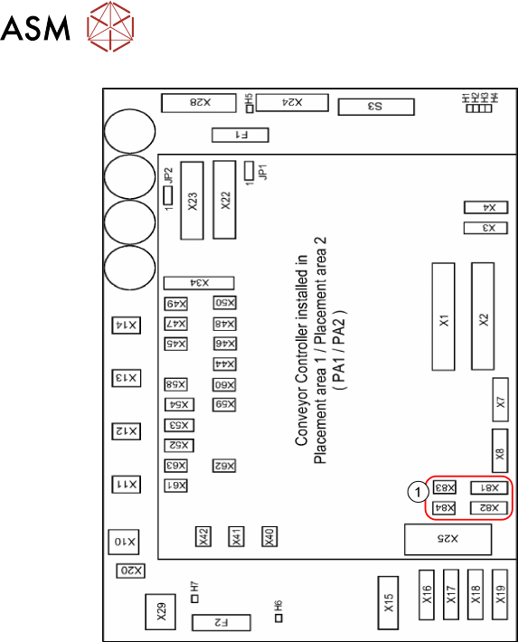
Fig.72: Conveyor control
1. Connectors for PCB barcode scanners
– Lane 1 / Single Conveyor:
PCB Barcode Scanner b 1 Lane
Bottom X81+83
PCB Barcode Scanner b 2 Lane
Top X82+84
– Lane 2 (Dual Conveyor only)
PCB Barcode Scanner b3 Lane Bot-
tom X81+83
PCB Barcode Scanner b4 Lane Top
X82+84
See also:
–
5.3.3 "Conveyor control TSP420
[03087642-xx]" [}125]
– 5.1 "Circuit Diagrams" [}113]
► Connect the cables to the connectors
X81 to X84(1).
► Repeat these steps for the second con-
veyor lane if required.
3.9 Performing Final Work
► Fit the covers and the lifting table plate.
► Fix the hand guard back onto the machine.
► Switch the machine back on and install the software.