00198371-01_UM_SWS-EN.pdf - 第10页
1 Introduction User manual SIPLACE Wafer System (SWS) 1.1 Overview Edition 04/2018 10 1.1 Overview Fig. 1.1 - 1 SWS - view from back 1 Fig. 1.1 - 2 SWS - view from front

User manual SIPLACE Wafer System (SWS) 1 Introduction
Edition 04/2018
9
1 Introduction
This user manual is a guide or reference work for operating and setting up the SIPLACE
®
Wafer
System (SWS).
This document is the original user manual.
The SIPLACE Wafer System (SWS) supplies the placement head of the SIPLACE CA4 V2 with
components (bare dies) directly from the wafer.
The wafer is fed in fully automatically from the wafer magazine and the components can then be
processed by the SIPLACE CA4 V2, using the customary placement procedure.
Flip chip process - function
The wafers are transported fully automatically from the wafer magazine to the wafer table. This
then positions the die concerned over the ejection system, which releases the die from the wafer
foil. After this release procedure, the flip unit nozzle takes the die, rotates it by 180° and makes it
available to the placement head for pickup.
The process spectrum is supplemented by the options:
– Die attach unit:
The die attach unit takes the die from the flip unit nozzle and turns it, so that it has the same
top-bottom orientation on the board as it had on the wafer.
– Linear Dipping Unit
The Linear Dipping Unit distributes precise layers of flux for the flip chip process. After taking
over from the flip unit the placement head dips the die in to the flux layer.
Installation in the SIPLACE CA4 V2
The SWS can be integrated into all four locations of the SIPLACE CA4 V2. There are two different
variants of the SWS:
SWS 12 (1/3) 1
SWS 12 (2/4) 1
SWS 12 (1/3) can be fitted to locations 1 and 3; SWS 12 (2/4) can be fitted to locations 2 and
4. 1
1 Introduction User manual SIPLACE Wafer System (SWS)
1.1 Overview Edition 04/2018
10
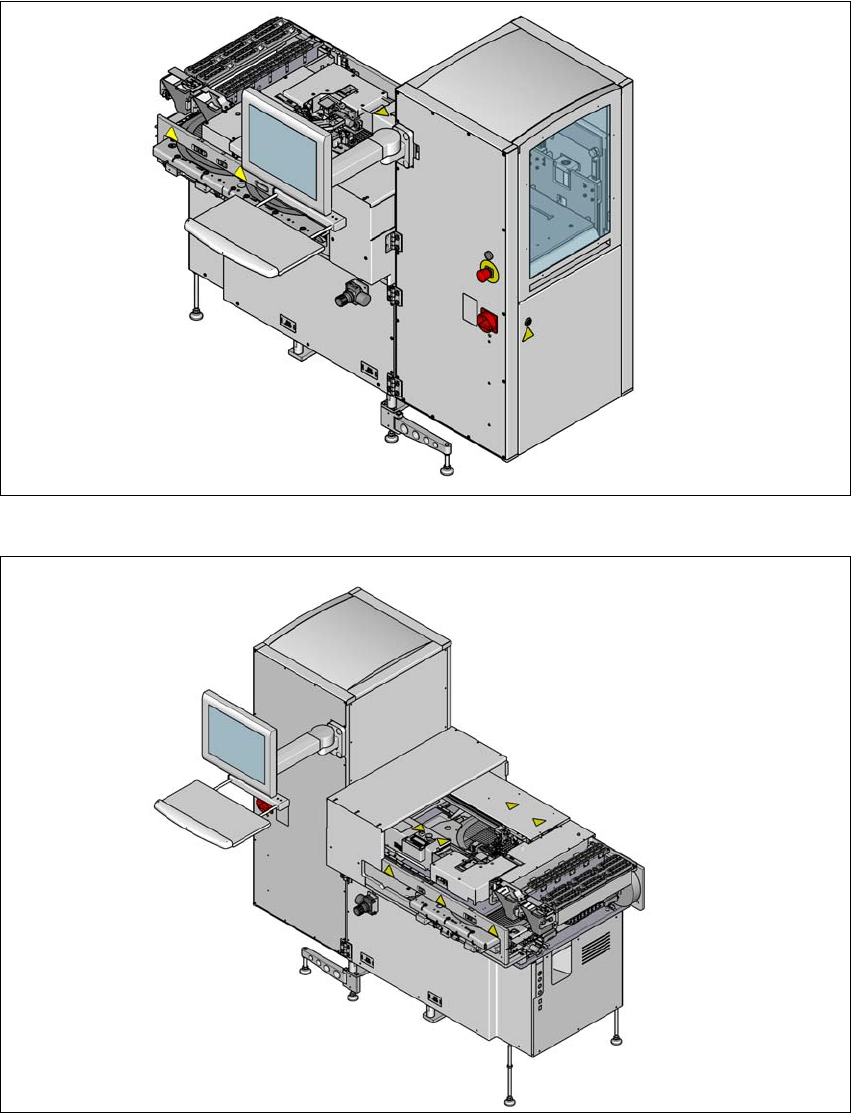
1.1 Overview
Fig. 1.1 - 1 SWS - view from back
1
Fig. 1.1 - 2 SWS - view from front
User manual SIPLACE Wafer System (SWS) 1 Introduction
Edition 04/2018 1.1 Overview
11
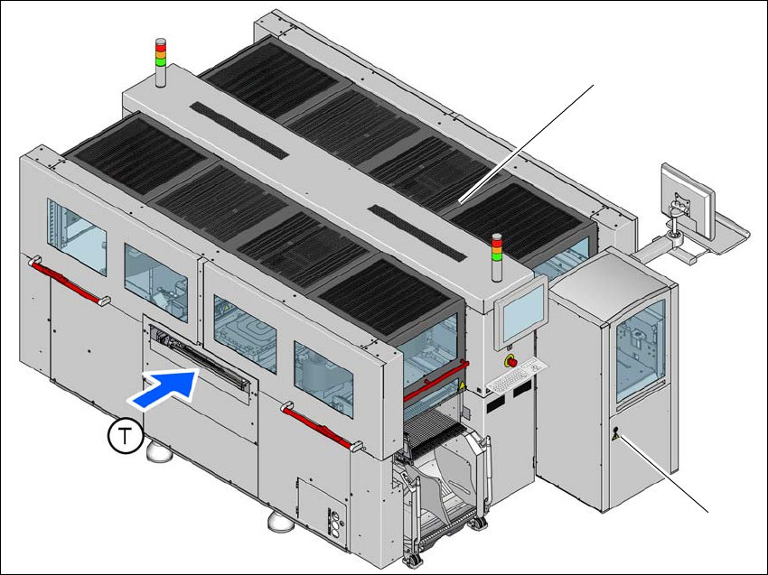
1.1.1 SIPLACE CA4 V2 with SWS
Various changes in hardware and software now make it possible to operate the SIPLACE CA4 V2
with the SIPLACE Wafer System (SWS).
The placement machine can be fitted with an SWS at one of the four locations, so that so-called
dies can be placed from wafers. This makes the components (dies) directly available to the place-
ment head, in wafers. Up to four SWS can be used with the SIPLACE CA4 V2. The SIPLACE CA4
V2 can also be operated with a combination of SWS and changeover tables or without an SWS
and with four changeover tables at the locations.
To ensure access to the installed SWS in the machine, a sliding cover has been fitted to the side
of each machine location.
For details, see the user manual for the SIPLACE CA4 V2, German [item no.: 00198381-xx], En-
glish [0198382-xx].
1
Fig. 1.1 - 3 SIPLACE CA4 V2 placement machine with one SIPLACE Wafer System (SWS)
(1) SIPLACE CA4 V2
(2) SIPLACE Wafer System (SWS) at location 2
(T) Direction of PCB transport
(1)
(2)