00198371-01_UM_SWS-EN.pdf - 第97页
User manual SIPLACE Wafer System (SWS) 5 SWS tasks Edition 04/2018 5.4 Checking and configuri ng the tools and nozzles on the flip unit 97 5.4 Checking and configurin g the tools and nozzles on the flip unit Open the s…
5 SWS tasks User manual SIPLACE Wafer System (SWS)
5.3 Setting up the needle configuration for the ejector system Edition 04/2018
96
Remove the black cap from the ejector system.
Insert all needles carefully into the segments and align the needles in about the same line.
Loosely tighten the grub screws. The needles still have to be movable.
5
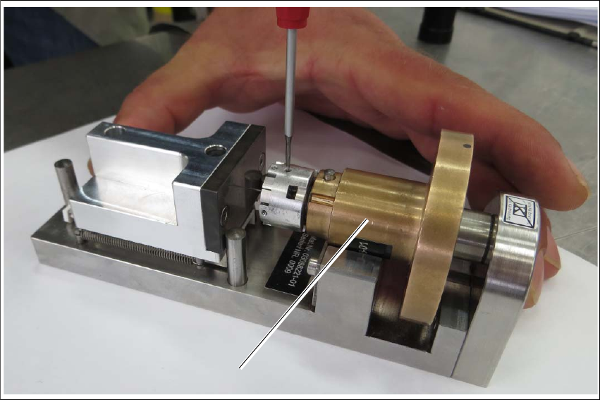
Fig. 5.3 - 4 Calibration standard for die ejector, magnetic
Insert the ejection system (1) into the calibration standard for the die ejector.
Place the ejector part into the device. The middle bolt of the device must be against the ejec-
tor plunger and the bronze part must be flexibly tensioned against the radius nib.
Turn the ejector part (bronze) into the required position.
Gently press the bronze part downwards - into the prisms.
Push the ejector needles into the required holes (you need to loosen the threaded pins).
Move the spring-tensioned adjustment slider towards the stop bolt and hold it tight.
Use a pair of tweezers to push the ejector needle towards the adjustment surface and tighten
the ejector needles and threaded pins (torque 10 Ncm).
1
User manual SIPLACE Wafer System (SWS) 5 SWS tasks
Edition 04/2018 5.4 Checking and configuring the tools and nozzles on the flip unit
97
5.4 Checking and configuring the tools and nozzles on
the flip unit
Open the side sliding cover on the SIPLACE CA4 V2.
5
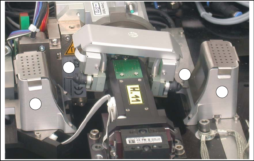
Fig. 5.4 - 1 Flip unit with nozzles and reject bins
Legend
5
Check the state and type of the nozzles and tools on the flip unit. If necessary, replace them
with new ones or those appropriate for the product.
You can either use the standard nozzles of the SIPLACE placement machines or rubber tips
with appropriate adapter nozzles.
Proceed with checking the reject bins.
(1) Nozzle segment 1 (2) Nozzle segment 2
(3) Reject bin
2
3
3
1
5 SWS tasks User manual SIPLACE Wafer System (SWS)
5.5 Checking the reject bin of the flip unit Edition 04/2018
98
5.5 Checking the reject bin of the flip unit
Check and empty the reject bin on the flip unit (item 3 in fig. 5.4 - 1).
When replacing the reject bins make sure that the underlying surface is clean and that the bin
is seated correctly in its fixation. Otherwise they are not recognized by the sensors.
Close the side sliding cover on the SIPLACE CA4 V2.
5.6 Refilling components at the SWS with the Wafer
Changer System
As soon as all wafers have been processed for a die type (note on the user interface), move
the magazine lift into the magazine change position, so that the magazine lift is level with the
height of the change position.
Remove the magazine from the magazine lift and replace the processed wafer.
Alternatively, you can also completely replace a processed wafer magazine with another
magazine which has already been prepared with new wafers.
After the wafer magazine has been replaced and the SWS sliding door closed, a magazine
scan will be automatically performed. 5
5.7 Shift changeover tasks
Check that the tools on the flip head are seated correctly (see section 5.4 on page 97) and
then check those on the die attach head, if required. ?
Remove any components from the machine.
Empty the component reject bin.
Check whether the correct multiple needle kit has been fitted (see section 5.3 on page 93).
Remove any flux from the LDU and clean the LDU thoroughly with alcohol, using the clean
cycle. For more details, see the ?SIPLACE LDU-X User Manual (item number of German ver-
sion [00196057-xx]).