00198371-01_UM_SWS-EN.pdf - 第104页
5 SWS tasks User manual SIPLACE Wafer System (SWS) 5.11 The user interface Edition 04/2018 104 5.1 1 The user interface The SWS GUI is the user interface for the SIPLAC E W afer System (SWS). After starting the SI- PLACE…
User manual SIPLACE Wafer System (SWS) 5 SWS tasks
Edition 04/2018 5.10 Switching on and off
103
5.10 Switching on and off
5.10.1 Switching the SWS on
First switch on all existing SWS modules for the SIPLACE CA4 V2.
The modules are starting up. As long as the placement machine is not yet switched on, an
error message will be displayed on the screen of the SWS module, which points out that
the safety circuit is not closed. 5
Switch the placement machine on.
The station computer will start. 5
As soon as the placement machine has been started up and the start button has been pressed,
the error message regarding the not-closed safety circuit vanishes from the SWS monitors. Initial-
ize the SWS module.
When the initializing process is completed, the SWSs are ready to operate and in standby.
5.10.2 Switching the SWS off
Switching off the SWS
Complete all processes running at the SWS modules.
Select Settings -> Shut down machine.
SWS GUI and Linux are shut down properly. 5
Switch off the SWS at the main switch.
Repeat this, if necessary, for each other SWS module.
5 SWS tasks User manual SIPLACE Wafer System (SWS)
5.11 The user interface Edition 04/2018
104
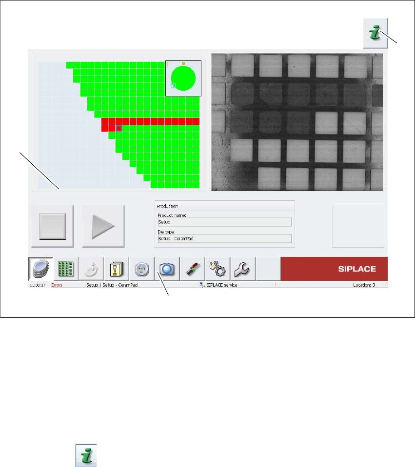
5.11 The user interface
The SWS GUI is the user interface for the SIPLACE Wafer System (SWS). After starting the SI-
PLACE Wafer System, the SWS GUI main view will automatically open.
5
Fig. 5.11 - 1 Main view of SWS GUI
Legend
(1) Help system
(2) Function toolbar
(3) Task and display section
For more information about the SWS GUI, refer to the context-sensitive Online Help.
Click on the Help System (1) icon to open the context-sensitive Online Help function.
Use the list of contents, index and the search function to view the contents of the Online Help.
(3)
(2)
(1)
User manual SIPLACE Wafer System (SWS) 6 Options
Edition 04/2018 6.1 Nozzle changer
105
6 Options
For the relevant configurations and other options, refer to the individual specifications.
6.1 Nozzle changer
Depending on the configuration of the placement heads on the SIPLACE CA4 V2, there may be
a nozzle changer attached to the SWS when it is used. The main difference between the nozzle
changers at an SWS and those at locations without SWS lies in the usage of a different reject bin
(03070917-01). The nozzle changers for the SWS are structured alike, the only difference is the
mirror-inversed position of the reject bins at the left-hand locations (1 and 3) and the right-hand
locations (2 and 4). Two rows of nozzle changers can be fitted to the SWS.
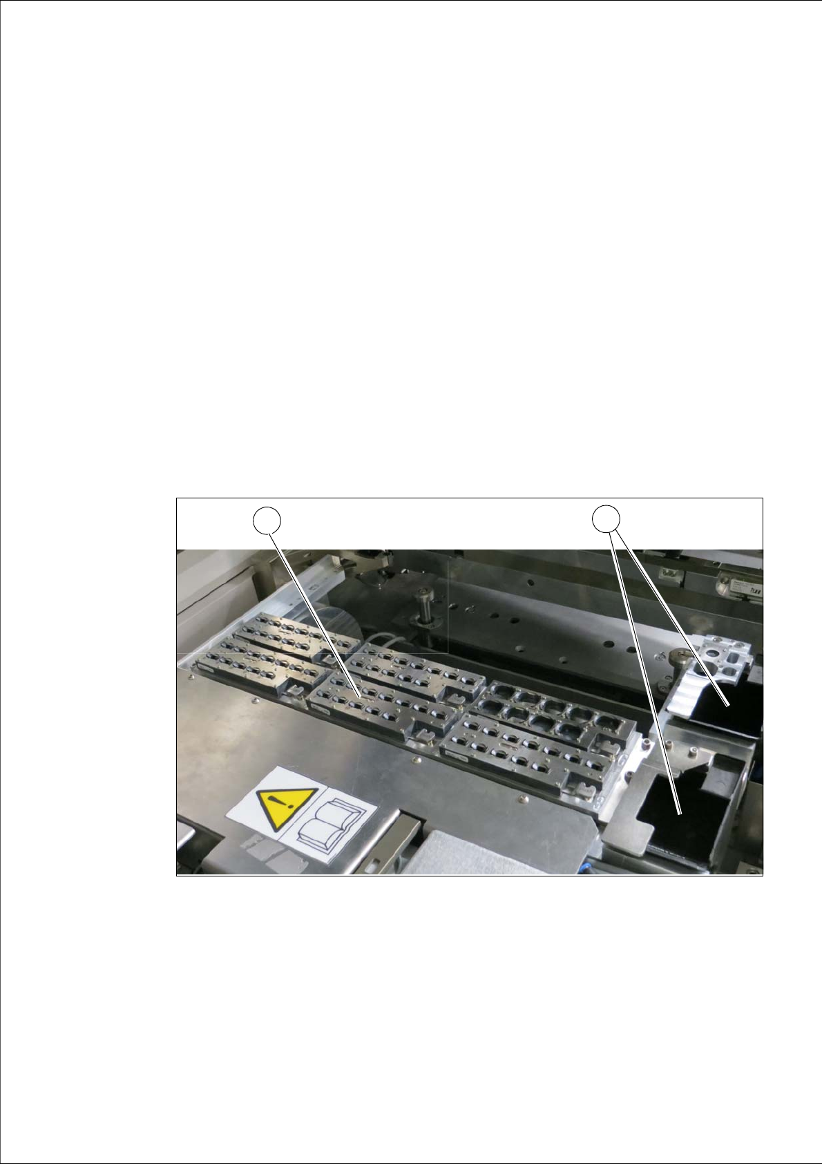
6.1.1 Position of nozzle changers - example
6
Fig. 6.1 - 1 Nozzle changer on the SWS - example
(1) Nozzle changer configuration (example)
(2) Component reject bin
1
2