00198371-01_UM_SWS-EN.pdf - 第75页
User manual SIPLACE Wafer System (SWS) 3 Technical data and assemblies Edition 04/2018 3.4 Description of the SWS modules 75 3.4.5 Die ejector According to the location (2 and 4 or 1 and 3) there ar e two different va ri…
3 Technical data and assemblies User manual SIPLACE Wafer System (SWS)
3.4 Description of the SWS modules Edition 04/2018
74
3
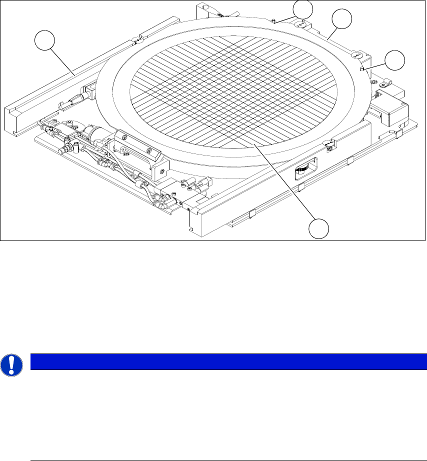
Fig. 3.4 - 5 Wafer support with wafer inserted (example for 12")
(1) Recess for the defined positioning on the pins of the locking bar
(2) Wafer locking bar
(3) Wafer
(4) Rail
3
PLEASE NOTE
Problems recognizing frames during clamping
If the wafer locking bar (2) has been incorrectly attached, the frame will not be recognized
correctly during clamping.
When using 8" wafer supports, make sure that the wafer locking bar (2) is attached in
a manner that allows the pins of the locking bar to engage with the recess on the wa-
fer frame.
3
1
4
2
1
User manual SIPLACE Wafer System (SWS) 3 Technical data and assemblies
Edition 04/2018 3.4 Description of the SWS modules
75
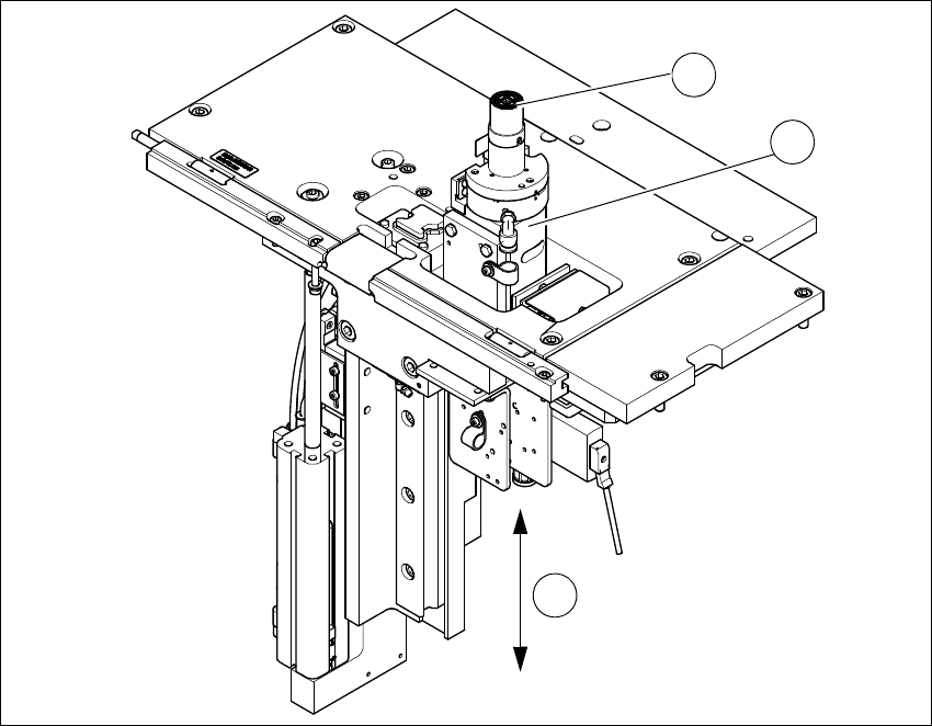
3.4.5 Die ejector
According to the location (2 and 4 or 1 and 3) there are two different variants that only differ in their
mirror-inverted arrangement of the modules.
3
Fig. 3.4 - 6 Main die ejector modules
(1) Ejector tool
(2) Z axis
(3) Z axis movement (pneumatic)
1
2
3
3 Technical data and assemblies User manual SIPLACE Wafer System (SWS)
3.4 Description of the SWS modules Edition 04/2018
76
3.4.6 Ejector tool
3
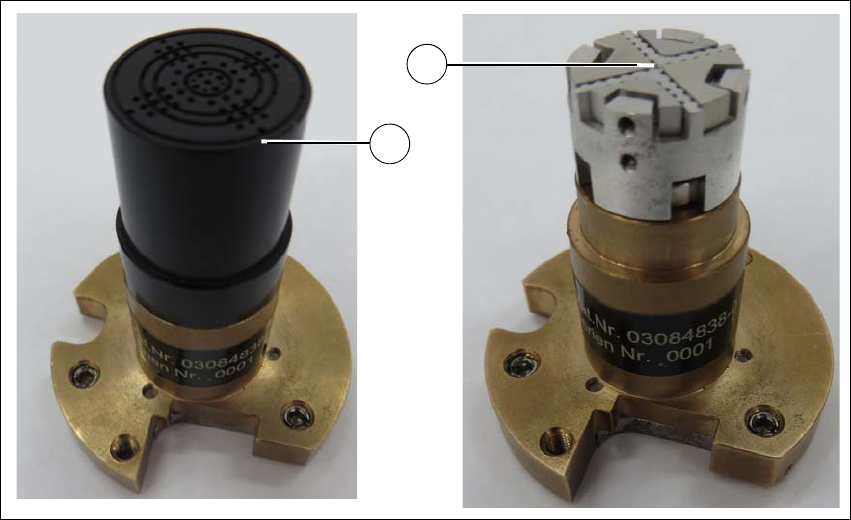
Fig. 3.4 - 7 Ejector tool
(1) Vacuum cap
(2) Guidance head for accommodating ejection needles
The die ejector is used to release the die from the wafer foil. It consists of the Z axis and the ejector
tool.
The ejector tool is positioned on the Z axis, fixed with prisms and held with magnets.
The wafer foil is picked up by vacuum suction at the vacuum cap, the needle system moves up
and releases the die from the wafer foil. The die can now be taken up by the nozzle of the flip unit.
The needle configuration of the ejector tool needs to be adjusted to the size of the die and can
therefore be configured to suit requirements.
The ejector tool can be equipped with 2 different needle types:
– Non-piercing needles
These cause the wafer foil to curve upwards and so release the die. The wafer foil is not
pierced in this case, so that the components are not touched by the needles.
– Piercing needles
These pierce the foil and lift the die directly off the foil.
1
2