00198371-01_UM_SWS-EN.pdf - 第25页
User manual SIPLACE Wafer System (SWS) 1 Introduction Edition 04/2018 1.2 Description of functions 25 1.2.4.3 Die att ach - transfer process 1 Fig. 1.2 - 8 Die attach - handover process (basic principle) (1) The die att …
1 Introduction User manual SIPLACE Wafer System (SWS)
1.2 Description of functions Edition 04/2018
24
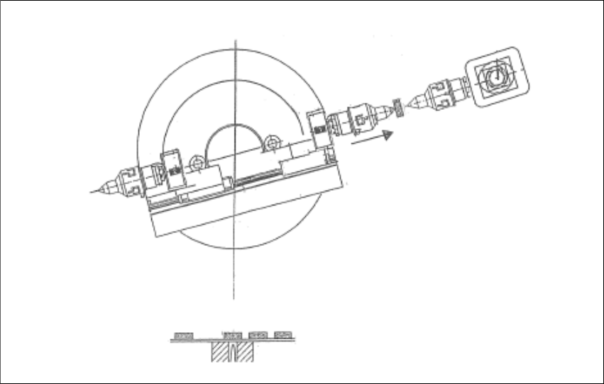
1.2.4.2 Flip chip segment 1 (transfer process)
1
Fig. 1.2 - 7 Flip chip segment 1 - transfer process (basic principle)
(1) The flipper transfer X axis of the flip chip swivel part segment 1 is moved to the transfer po-
sition.
(1)
User manual SIPLACE Wafer System (SWS) 1 Introduction
Edition 04/2018 1.2 Description of functions
25
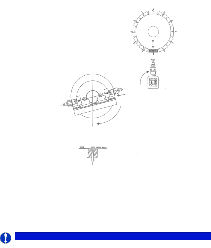
1.2.4.3 Die attach - transfer process
1
Fig. 1.2 - 8 Die attach - handover process (basic principle)
(1) The die attach rotates to the transfer position.
(2) The SIPLACE head picks the chip up from the die attach segment and rotates to the next star
position.
(3) At the same time the flipper transfer X axis pulls segment no. 1 back into the home position.
(4) The flip chip unit - segment no. 1 rotates to the pickup position and picks up the next chip.
1
PLEASE NOTE
While using the die attach unit only the segment no.1 of the flip chip unit is active.
(1)
(2)
(3)
(4)
1 Introduction User manual SIPLACE Wafer System (SWS)
1.2 Description of functions Edition 04/2018
26
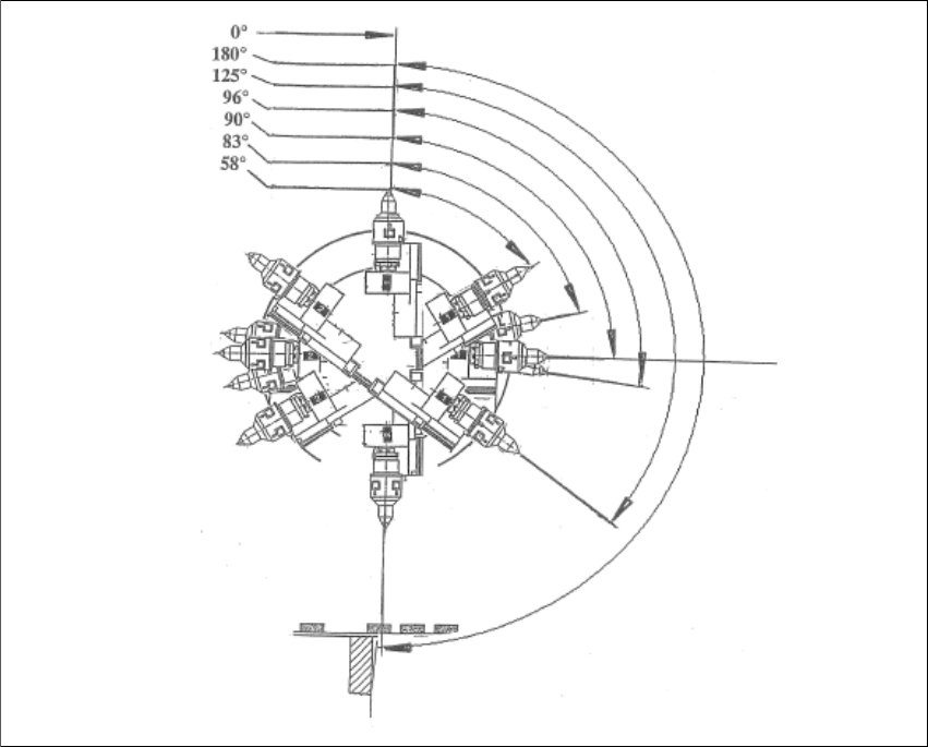
1.2.4.4 Flip chip encoded positions (after calibration)
1
1
Fig. 1.2 - 9 Flip chip encoded positions - after calibration (basic principle)
0°
Home sensor position
180°
Transfer position, segment 1
125°
Camera "free" position, segment 1
96°
Discharge position, segment 1
105°
Home offset position
83°
Discharge position, segment 2
58°
Camera "free" position, segment 2