00198371-01_UM_SWS-EN.pdf - 第27页
User manual SIPLACE Wafer System (SWS) 1 Introduction Edition 04/2018 1.2 Description of functions 27 1 Fig. 1.2 - 10 Initialization of flip rotation axis (basic principle) (1) Mechanical stop (2) Home sensor The home se…
1 Introduction User manual SIPLACE Wafer System (SWS)
1.2 Description of functions Edition 04/2018
26
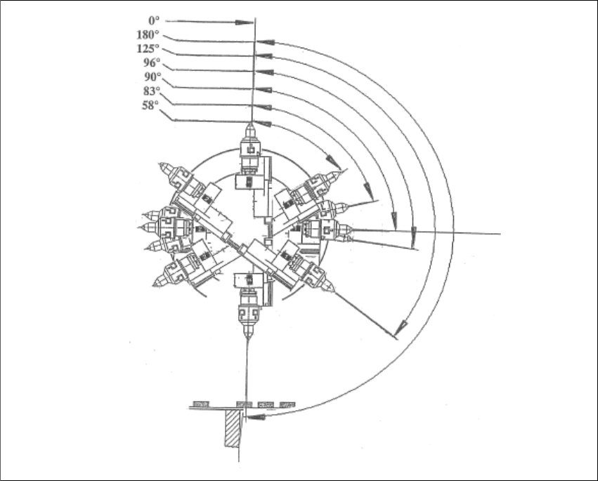
1.2.4.4 Flip chip encoded positions (after calibration)
1
1
Fig. 1.2 - 9 Flip chip encoded positions - after calibration (basic principle)
0°
Home sensor position
180°
Transfer position, segment 1
125°
Camera "free" position, segment 1
96°
Discharge position, segment 1
105°
Home offset position
83°
Discharge position, segment 2
58°
Camera "free" position, segment 2
User manual SIPLACE Wafer System (SWS) 1 Introduction
Edition 04/2018 1.2 Description of functions
27
1
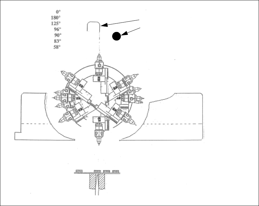
Fig. 1.2 - 10 Initialization of flip rotation axis (basic principle)
(1) Mechanical stop
(2) Home sensor
The home sensor is used to initialize the flip rotation axis. During the initialization, the rotation axis
travels slowly until the home sensor triggers. Afterwards the first zero pulse is looked up in an area
of 0-30° of the rotation axis. Through that the zero position of the flip rotation axis is defined.
Reject bin
Segment no. 2
Reject bin
Segment no. 1
1. Mechanical stop
2. Home sensor
1 Introduction User manual SIPLACE Wafer System (SWS)
1.2 Description of functions Edition 04/2018
28
1
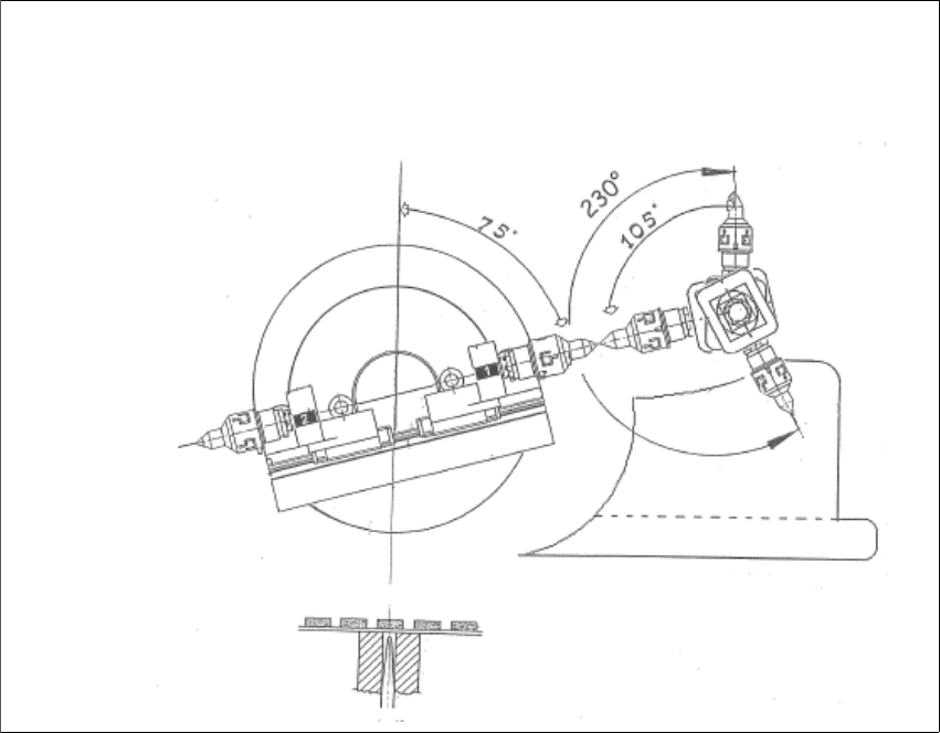
Fig. 1.2 - 11 Positions flip head/die attach segment
The transfer position of the flip head, the pick up and discharge position, as well as the transfer
position of the die attach segment to the placement head.
75°
Flipper transfer position
105°
Die attach transfer position
230°
Air kiss position die attach