00198371-01_UM_SWS-EN.pdf - 第94页
5 SWS tasks User manual SIPLACE Wafer System (SWS) 5.3 Setting up the needle configuration for the ejector system Edition 04/2018 94 5 Fig. 5.3 - 1 Ejector system for die ejector, magnetic Pull out the eje ction system…
User manual SIPLACE Wafer System (SWS) 5 SWS tasks
Edition 04/2018 5.3 Setting up the needle configuration for the ejector system
93
5.3 Setting up the needle configuration for the ejector
system
In the SWS GUI, switch over to the Manual operations -> Wafer handling view and click on
the Go to change position button.
The wafer table is removed.
In the SWS GUI, switch over to the Manual operations -> Die handling view and select the
Ejection unit tab.
Click on the button.
The die ejector is moved upwards, so that it can be accessed.
5
Open the side sliding cover on the SIPLACE CA4 V2.
5
CAUTION
Risk of damage!
When moving the wafter table manually, the ejector system which was moved upwards
could collide with the wafer table and be damaged.
Do not push the wafer table manually.
CAUTION
Risk of injury from sharp needles
There is a risk of injury from the sharp needles on the ejector system.
5 SWS tasks User manual SIPLACE Wafer System (SWS)
5.3 Setting up the needle configuration for the ejector system Edition 04/2018
94
5
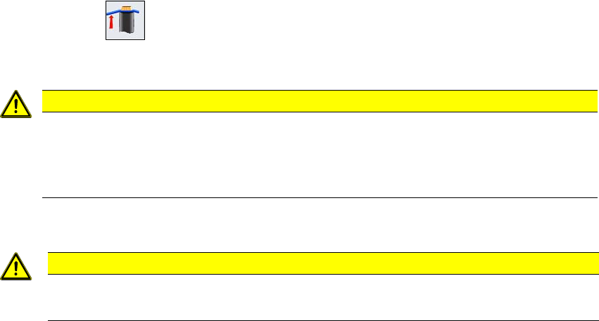
Fig. 5.3 - 1 Ejector system for die ejector, magnetic
Pull out the ejection system (1).
Pull the black cap (2) off to reveal the needles in the guidance head (3).
The needles can be clamped into 4 sectors. There can be one needle in the middle. 5
Grub screws (4) clamp the needles into place at the 4 segments.
The middle needle is clamped into place with the lower grub screw (5). 5
Fit the relevant needles for your application in the openings of the 4 segments.
5
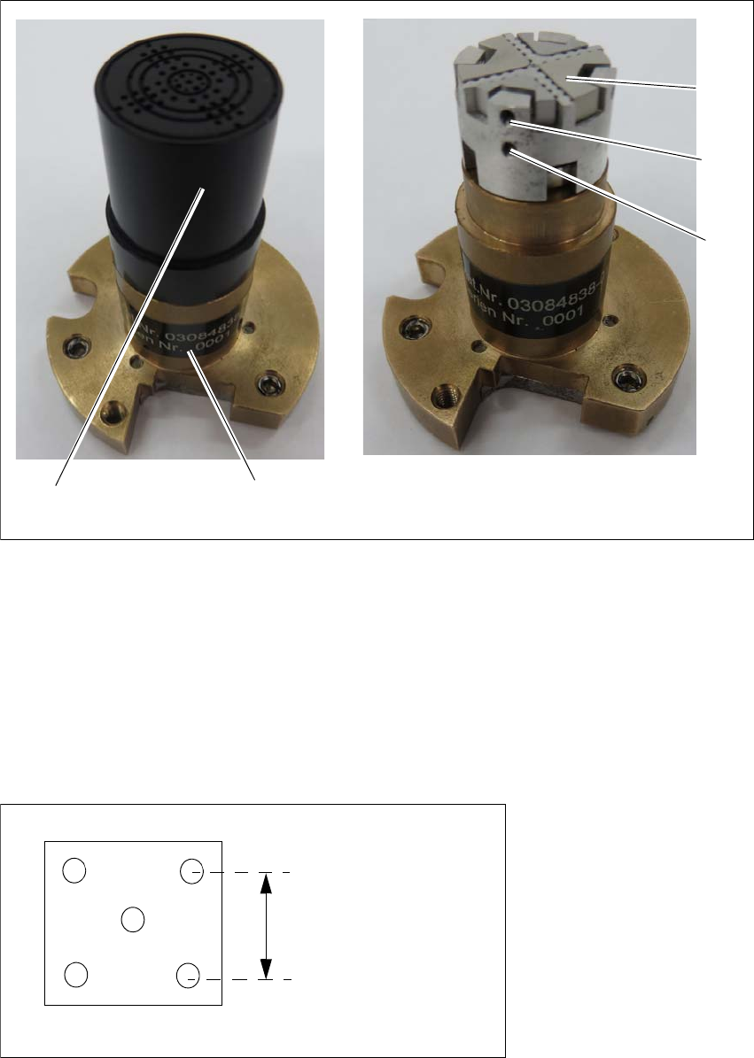
Fig. 5.3 - 2 Diagram of needle position (example)
1
3
2
4
5
3.5 mm or 2 mm
User manual SIPLACE Wafer System (SWS) 5 SWS tasks
Edition 04/2018 5.3 Setting up the needle configuration for the ejector system
95
– Ejector system 5 needles with 3.5 mm spacing (00385535-02)
– Ejector system 5 needles with 2 mm spacing (00386908-02)
Carry out the following adjustments with the relevant calibration standard.
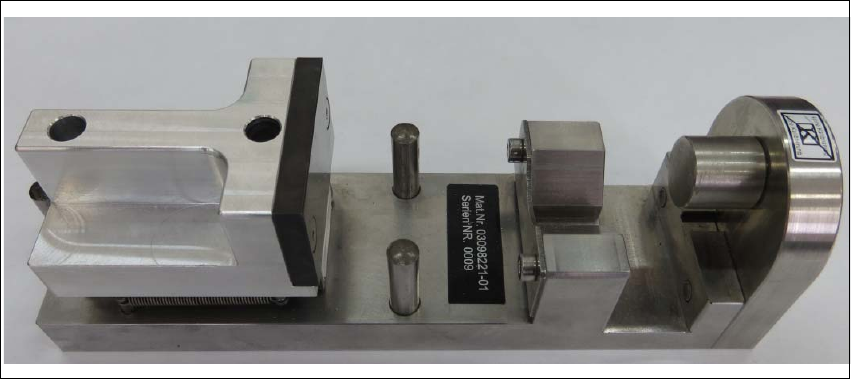
5.3.1 Setting the needle with the calibration standard 03098221-xx
For die ejector, magnetic Item no. 03098221-xx
For die ejector with bayonet lock (old); Item no. 03080191-xx
Equipment
– Needles as spare parts
– Calibration standard for the die ejector, magnetic (03098221-xx)
With the help of the calibration standard for the die ejector all needles are adjusted into
a defined height and common level. 5
5
Fig. 5.3 - 3 Calibration standard for the die ejector, magnetic - item number 03098221-xx