00198371-01_UM_SWS-EN.pdf - 第68页
3 Technical data and assemblies User manual SIPLACE Wafer System (SWS) 3.3 Overview of the modules Edition 04/2018 68 3 Fig. 3.3 - 3 Overview of SWS assemblies (1) Clamping unit (2) W afer camera (3) Flip unit (4) W afer…
User manual SIPLACE Wafer System (SWS) 3 Technical data and assemblies
Edition 04/2018 3.3 Overview of the modules
67
3
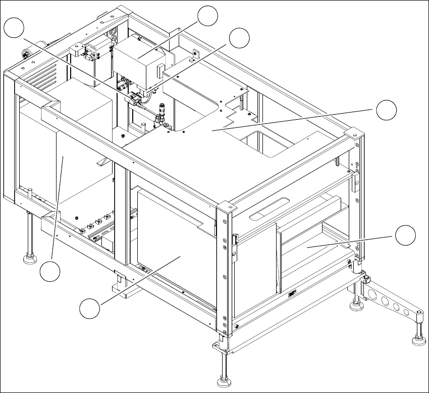
Fig. 3.3 - 2 SWS supply unit from front
3
(1) Electronic unit front (2) Computer unit
(3) Transformer (4) Pressure switch
(5) Mains filter (6) Solenoid valve
(7) Cover
3
2
1
7
6
5
4
3 Technical data and assemblies User manual SIPLACE Wafer System (SWS)
3.3 Overview of the modules Edition 04/2018
68
3
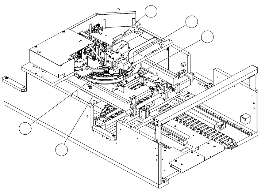
Fig. 3.3 - 3 Overview of SWS assemblies
(1) Clamping unit (2) Wafer camera
(3) Flip unit (4) Wafer support
(5) Guidance
4
3
1
2
5
User manual SIPLACE Wafer System (SWS) 3 Technical data and assemblies
Edition 04/2018 3.4 Description of the SWS modules
69
3.4 Description of the SWS modules
3.4.1 Supply unit
3
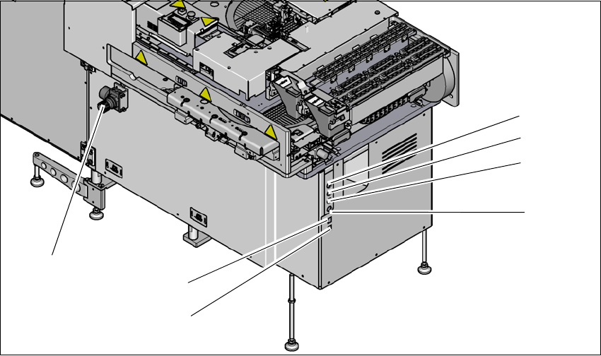
Fig. 3.4 - 1 Supply unit (example SWS 2/4)
3
(1) Setting the air blast for flip head segments
or die attach segments
(2) Voltage supply
(3) Interface safety cutoff with SIPLACE CA4
V2
(4) CAN bus (for SW 605.x only)
(5) Opening for compressed air hose from the
SIPLACE CA4 V2
(6) LAN1 - communication with external map
server
(7) LAN2 - communication with SIPLACE CA4
V2 and possible with other SWS
(1)
(2)
(3)
(4)
(6)
(7)
(5)