00198371-01_UM_SWS-EN.pdf - 第18页
1 Introduction User manual SIPLACE Wafer System (SWS) 1.2 Description of functions Edition 04/2018 18 1.2.3 Basic die present ation process The basic die presenta tion process supported by the SWS can be divid ed into 3 …

User manual SIPLACE Wafer System (SWS) 1 Introduction
Edition 04/2018 1.2 Description of functions
17
1.2.2 Basic SWS Functions
The main die handling components are the wafer table, the magazine lift, the ejection system, the
flip unit and the control unit with corresponding SWS software.
The wafer with the relevant die is loaded from the magazine and fixed onto the wafer table. The
wafer table places the die using the ejector system, which releases the die from the wafer foil, and
transfers it to the flip unit.
The flip unit then processes this using two different functions:
– The flip unit rotates the die by 180° and makes this available for pickup by the placement
head.
or 1
– The flip unit transfers it to the die attach unit. The placement head approaches this and the
die is placed on the board in the same position as it was on the wafer.
The SIPLACE CA4 V2 uses a high precision SIPLACE placement head which has been specifi-
cally selected for maximum accuracy and fulfillment of all requirements in normal and restricted
conditions (see "Scope of delivery and services" for details of restrictions).
1
The following options are available to support the whole spectrum of process-oriented functions:
– Linear dipping unit
– Die attach unit
– Barcode scanner
– Wafer stretcher
– Inspection camera
PLEASE NOTE
All movable positioning axes in the SWS are servo axes!
1 Introduction User manual SIPLACE Wafer System (SWS)
1.2 Description of functions Edition 04/2018
18
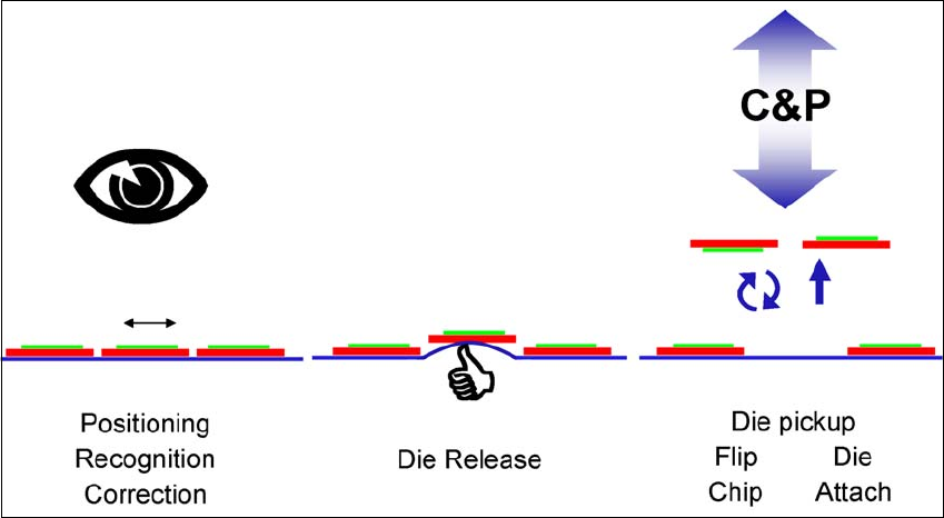
1.2.3 Basic die presentation process
The basic die presentation process supported by the SWS can be divided into 3 main steps:
– Die recognition and positioning for ejection (inc. inkspot recognition)
– Ejection process
– Die attach or flip chip process.
1
Fig. 1.2 - 1 Basic die presentation process (basic principle)
There are two main ways to process dies:
– Flip chip process
– Die attach process
User manual SIPLACE Wafer System (SWS) 1 Introduction
Edition 04/2018 1.2 Description of functions
19
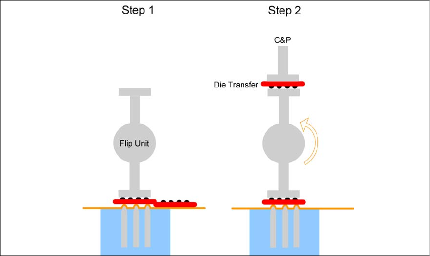
1.2.3.1 Flip chip process
The flip chip process is the standard method for SWS. The die is rotated by 180° before placement
(face down placement).
1
Fig. 1.2 - 2 Flip chip process (basic principle)
The flip chip process steps are:
– Step 1: Die release
– Step 2: The die is rotated by 180° and is passed on to the placement head. Parallel to this,
the next die is taken up by the second nozzle of the flip unit.