00198371-01_UM_SWS-EN.pdf - 第95页
User manual SIPLACE Wafer System (SWS) 5 SWS tasks Edition 04/2018 5.3 Setting up the needle configuration for th e ejector system 95 – Ejector system 5 needles with 3.5 mm spacing (003855 35-02) – Ejector system 5 needl…
5 SWS tasks User manual SIPLACE Wafer System (SWS)
5.3 Setting up the needle configuration for the ejector system Edition 04/2018
94
5
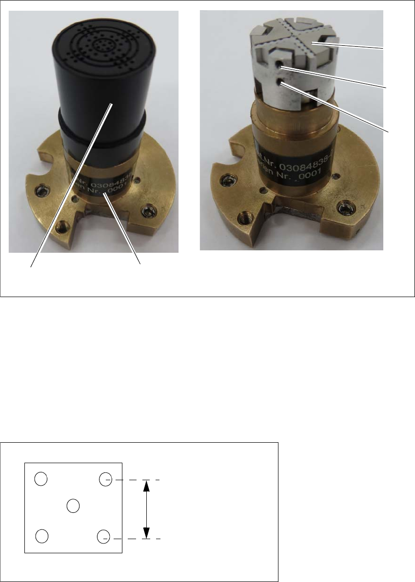
Fig. 5.3 - 1 Ejector system for die ejector, magnetic
Pull out the ejection system (1).
Pull the black cap (2) off to reveal the needles in the guidance head (3).
The needles can be clamped into 4 sectors. There can be one needle in the middle. 5
Grub screws (4) clamp the needles into place at the 4 segments.
The middle needle is clamped into place with the lower grub screw (5). 5
Fit the relevant needles for your application in the openings of the 4 segments.
5
Fig. 5.3 - 2 Diagram of needle position (example)
1
3
2
4
5
3.5 mm or 2 mm
User manual SIPLACE Wafer System (SWS) 5 SWS tasks
Edition 04/2018 5.3 Setting up the needle configuration for the ejector system
95
– Ejector system 5 needles with 3.5 mm spacing (00385535-02)
– Ejector system 5 needles with 2 mm spacing (00386908-02)
Carry out the following adjustments with the relevant calibration standard.
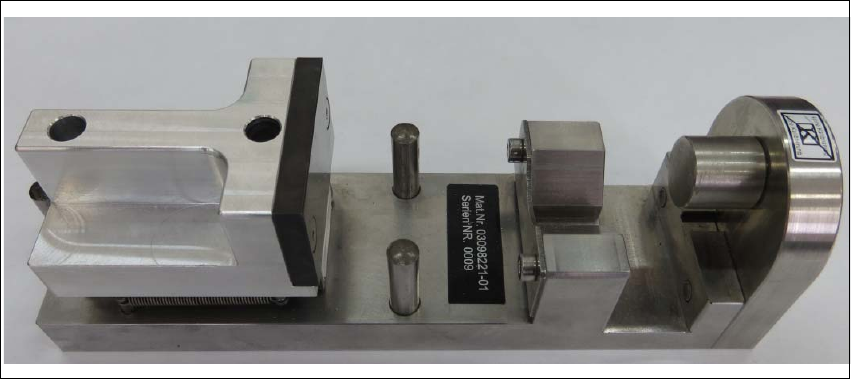
5.3.1 Setting the needle with the calibration standard 03098221-xx
For die ejector, magnetic Item no. 03098221-xx
For die ejector with bayonet lock (old); Item no. 03080191-xx
Equipment
– Needles as spare parts
– Calibration standard for the die ejector, magnetic (03098221-xx)
With the help of the calibration standard for the die ejector all needles are adjusted into
a defined height and common level. 5
5
Fig. 5.3 - 3 Calibration standard for the die ejector, magnetic - item number 03098221-xx
5 SWS tasks User manual SIPLACE Wafer System (SWS)
5.3 Setting up the needle configuration for the ejector system Edition 04/2018
96
Remove the black cap from the ejector system.
Insert all needles carefully into the segments and align the needles in about the same line.
Loosely tighten the grub screws. The needles still have to be movable.
5
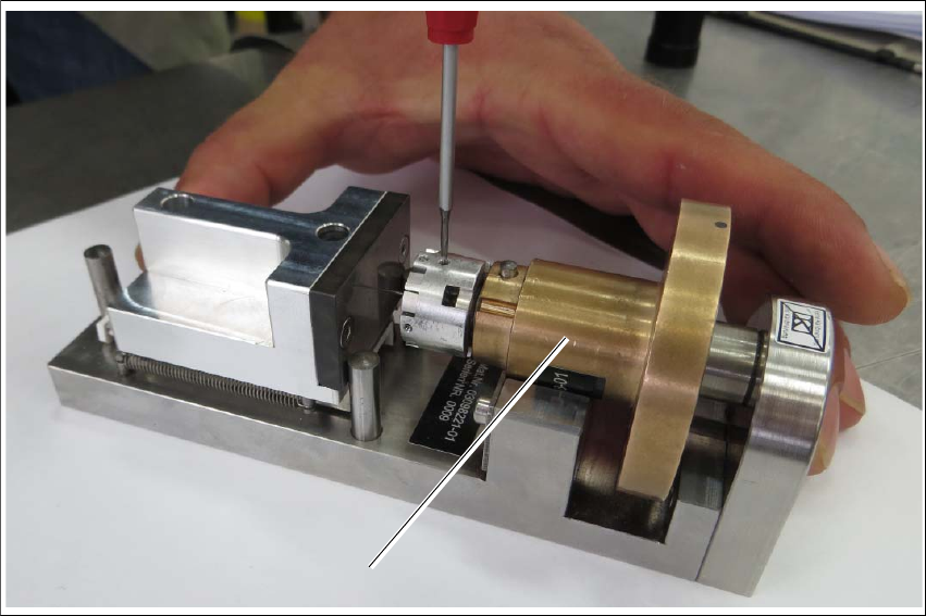
Fig. 5.3 - 4 Calibration standard for die ejector, magnetic
Insert the ejection system (1) into the calibration standard for the die ejector.
Place the ejector part into the device. The middle bolt of the device must be against the ejec-
tor plunger and the bronze part must be flexibly tensioned against the radius nib.
Turn the ejector part (bronze) into the required position.
Gently press the bronze part downwards - into the prisms.
Push the ejector needles into the required holes (you need to loosen the threaded pins).
Move the spring-tensioned adjustment slider towards the stop bolt and hold it tight.
Use a pair of tweezers to push the ejector needle towards the adjustment surface and tighten
the ejector needles and threaded pins (torque 10 Ncm).
1