00198371-01_UM_SWS-EN.pdf - 第82页
3 Technical data and assemblies User manual SIPLACE Wafer System (SWS) 3.4 Description of the SWS modules Edition 04/2018 82 3 Fig. 3.4 - 12 Main gripper modules (location 1,3) (1) Gripper (2) T oothed belt axis (3) Inse…
User manual SIPLACE Wafer System (SWS) 3 Technical data and assemblies
Edition 04/2018 3.4 Description of the SWS modules
81
3.4.7.3 Wafer changer
According to the location (2 and 4 or 1 and 3) there are two different versions of the wafer changer.
3
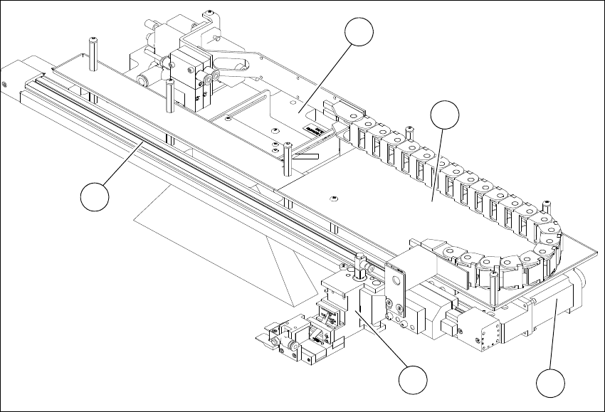
Fig. 3.4 - 11 Main gripper modules (location 2,4)
3
(1) Gripper (2) Toothed belt axis
(3) Installation location for barcode scanner
(optional)
(4) AD-MOT board below the cover
(5) Motor with coupling
1
4
5
3
2
3 Technical data and assemblies User manual SIPLACE Wafer System (SWS)
3.4 Description of the SWS modules Edition 04/2018
82
3
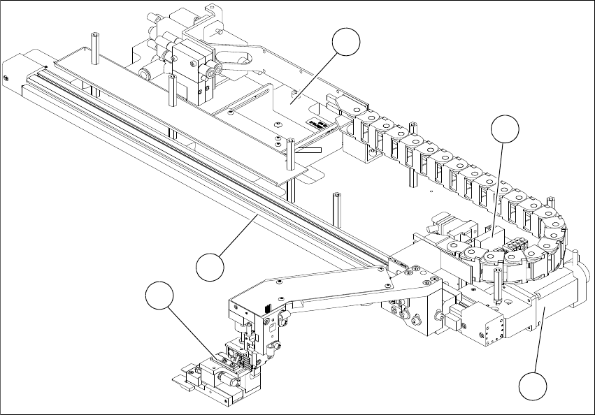
Fig. 3.4 - 12 Main gripper modules (location 1,3)
(1) Gripper (2) Toothed belt axis
(3) Insertion location for barcode scanner
(optional)
(4) AD-MOT board
(5) Motor with coupling
1
2
4
5
3
User manual SIPLACE Wafer System (SWS) 4 Setting up and commissioning
Edition 04/2018 4.1 Delivery configuration and transportation of SWS
83
4 Setting up and commissioning
4.1 Delivery configuration and transportation of SWS
4.1.1 Shipping packaging
Within Europe the SIPLACE Wafer System is transported on a wooden pallet and is wrapped in
plastic foil. Outside Europe, the SIPLACE Wafer System is supplied in a wooden crate mounted
on a stable wooden pallet.
4.1.1.1 Dimensions of transportation packaging
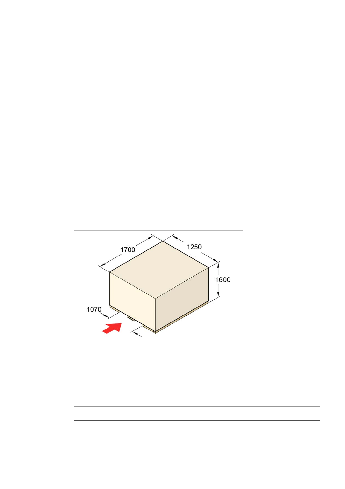
The dimension of the wooden transport crate are as follows:
Length 1700 mm
Width 1250 mm
Height 1600 mm
4
4
Fig. 4.1 - 1 Transport crate SWS - dimensions in millimeters
4.1.1.2 SIPLACE Wafer System weight when ready for dispatch
The following table contains the weights of the SIPLACE Wafer System prepared for dispatch, in-
cluding packaging.
fork-lift attachment
point
Dispatch within Europe Dispatch overseas
SIPLACE Wafer System 390 kg 473 kg