00198371-01_UM_SWS-EN.pdf - 第66页
3 Technical data and assemblies User manual SIPLACE Wafer System (SWS) 3.3 Overview of the modules Edition 04/2018 66 3.3 Overview of the modules 3 Fig. 3.3 - 1 Overview of the SWS 3 (1) Gripper (2) Flip u nit (3) Inst a…
User manual SIPLACE Wafer System (SWS) 3 Technical data and assemblies
Edition 04/2018 3.2 Ambient conditions and connection values
65
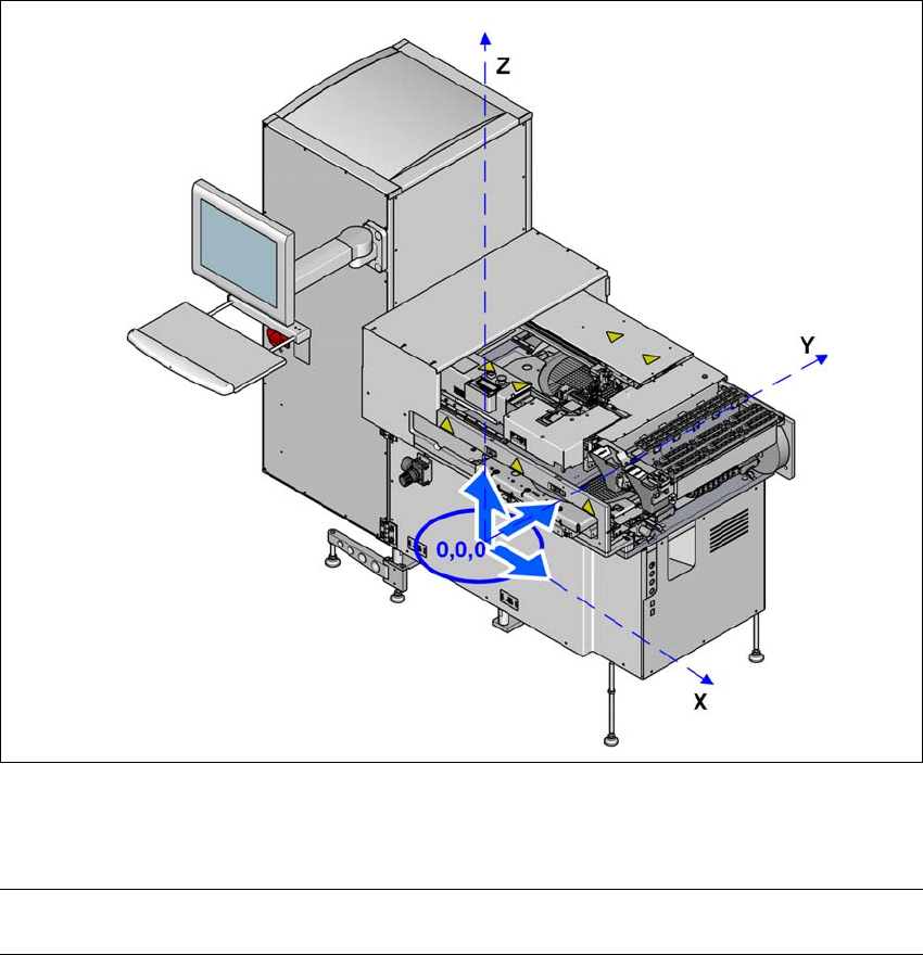
3.2.6 Center of gravity for SWS
3
Fig. 3.2 - 2 Center of gravity for SWS
3
Center of gravity coordinates:
SWS X coordinate
Y coordinate
0 mm
650 mm

3 Technical data and assemblies User manual SIPLACE Wafer System (SWS)
3.3 Overview of the modules Edition 04/2018
66
3.3 Overview of the modules
3
Fig. 3.3 - 1 Overview of the SWS
3
(1) Gripper (2) Flip unit
(3) Installation position for options (die attach
unit or LDU X)
(4) Die ejector
(5) Supply unit (6) X unit
(7) Magazine lift
1
2
3
4
5
6
7
User manual SIPLACE Wafer System (SWS) 3 Technical data and assemblies
Edition 04/2018 3.3 Overview of the modules
67
3
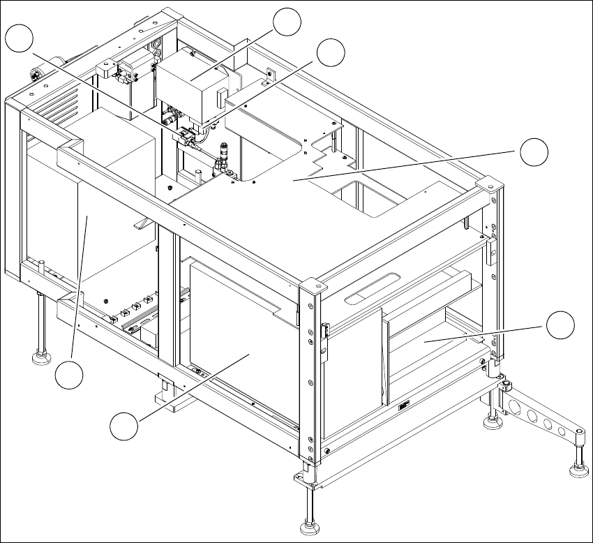
Fig. 3.3 - 2 SWS supply unit from front
3
(1) Electronic unit front (2) Computer unit
(3) Transformer (4) Pressure switch
(5) Mains filter (6) Solenoid valve
(7) Cover
3
2
1
7
6
5
4