00194845-0302_MM_D1_D2_EN.pdf - 第5页
SIPLA CE D1 / D2 1 Safety instructions 02/2010 EN Edition 5 1 Safety in structions 1 Fig. 1.0 - 1 Position of switches and buttons - Vi ew of the PCB output side (1) Main power sw itch (2) S t art button (white) on the o…
Preventive Maintenance D1 / D2
02/2010 Edition
4
SIPLACE D1 / D2 1 Safety instructions
02/2010 EN Edition
5
1 Safety instructions
1
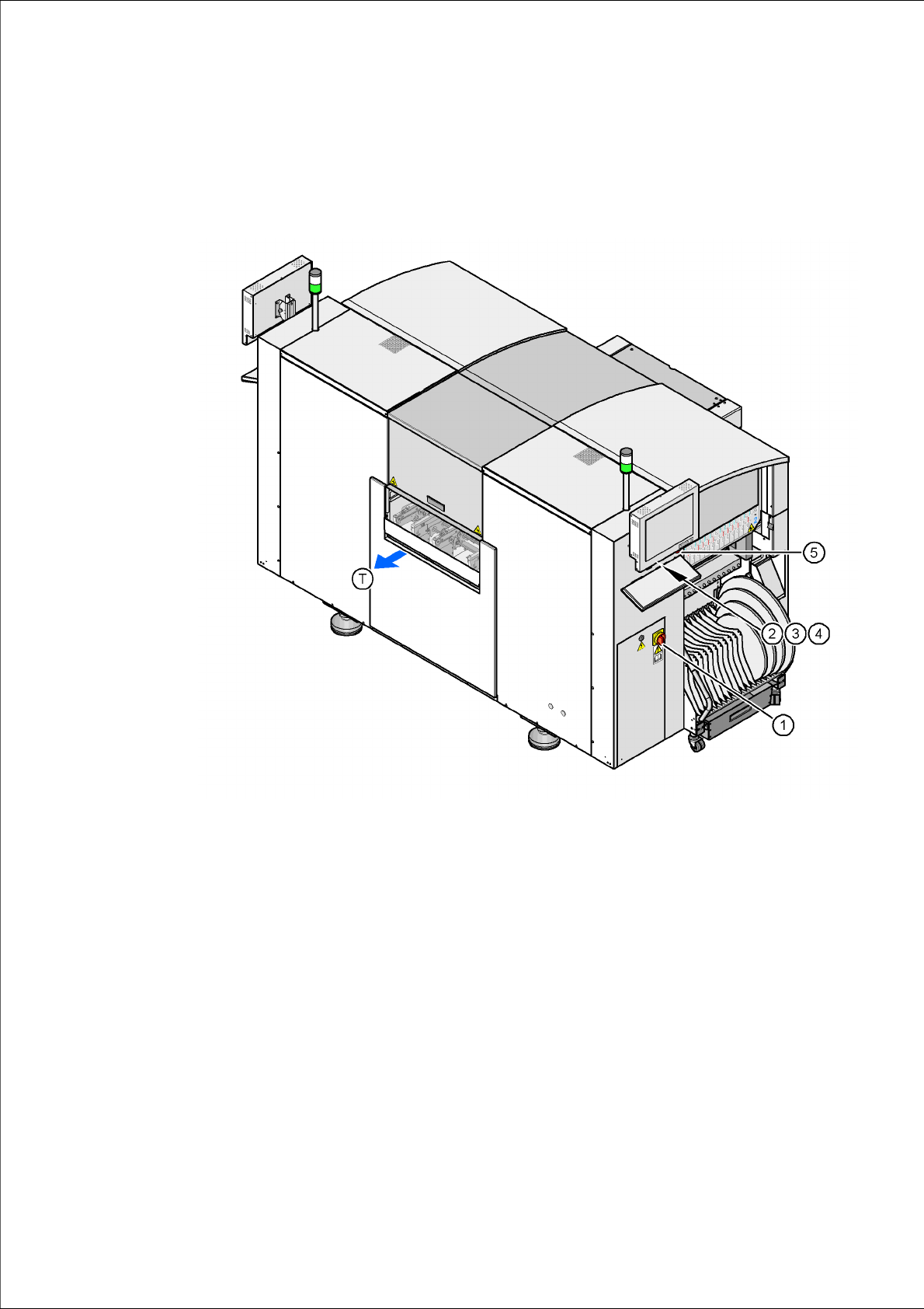
Fig. 1.0 - 1 Position of switches and buttons - View of the PCB output side
(1) Main power switch
(2) Start button (white) on the operator panel on the power supply side
(3) Stop button (black) on the operator panel on the power supply side
(4) Component counter on the operator panel on the power supply side
(5) EMERGENCY STOP button on the operator panel on the power supply side
(T) PCB transport direction
1 Safety instructions SIPLACE D1 / D2
02/2010 EN Edition
6
1
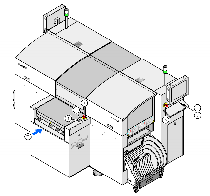
Fig. 1.0 - 2 Position of switches and buttons - View of the PCB input side
(1) EMERGENCY STOP button on the input side
(2) Start button (white) on the input side
(3) Stop button (white) on the input side
(4) Start button (white) on the operator panel on the compressed air unit side
(5) Stop button (black) on the operator panel on the compressed air unit side
(6) EMERGENCY STOP button on the operator panel on the compressed air unit side
(T) PCB transport direction
1
1
1
1