00198377-01_SM_JTF-ML2_en.pdf - 第10页
1 Introduction 1.1 Safety Instructions 10 Service Manual SIPLACE JTF-ML2 08/2017 Fig.4: Conveyor belt rollers Fig.5: Pusher Fig.6: Side tray clamp 1.1.5 Safety Instructions for Transporting the Module Fig.7: Holding …
1 Introduction
1.1 Safety Instructions
Service Manual SIPLACE JTF-ML2 08/2017 9
1.1.3.3 Safety of Plant and Equipment
► Never make changes, however minor, unless you are totally aware of the effect they will have
on the overall functioning of the module and system!
► The modules must always be set up, retooled and maintained by appropriately trained person-
nel.
► Do not make modifications to the safety equipment. In particular, NEVER deactivate circuit-
breakers or remove safety devices.
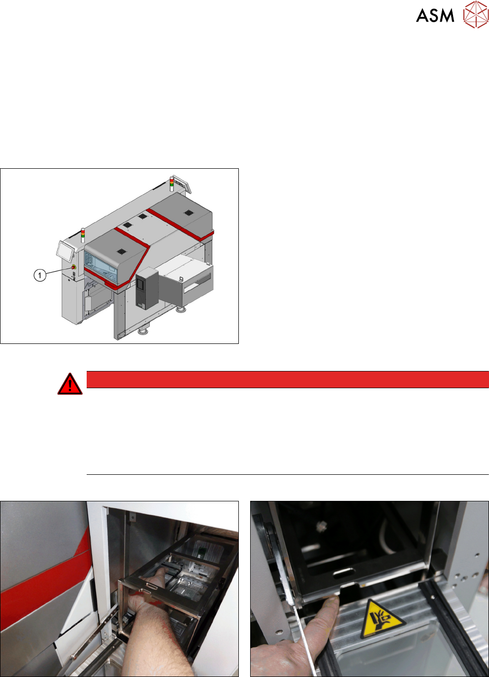
1.1.4 Danger of Crushing at the SIPLACE JTF-ML2
Fig.1: EMERGENCY STOP button
The SIPLACE JTF-ML2 (JEDEC tray feeder) stops
when the EMERGENCY STOP button (1) is pressed.
DANGER
Danger of crushing
There is a risk of injuries by pinch points or a risk of crushing by reaching into the feeder or
from loose clothing which could get into the feeder during operation.
► Observe correct handling and the safety instructions.
► Do not reach into the feeder while it is running.
► Maintain an adequate safety distance.
Areas of the SIPLACE JTF-ML2 at which there is a danger of crushing
Fig.2: Do not reach into the JTF_ML2 or into the machine
through the JTF_ML2.
Fig.3: Moving magazine
1 Introduction
1.1 Safety Instructions
10 Service Manual SIPLACE JTF-ML2 08/2017
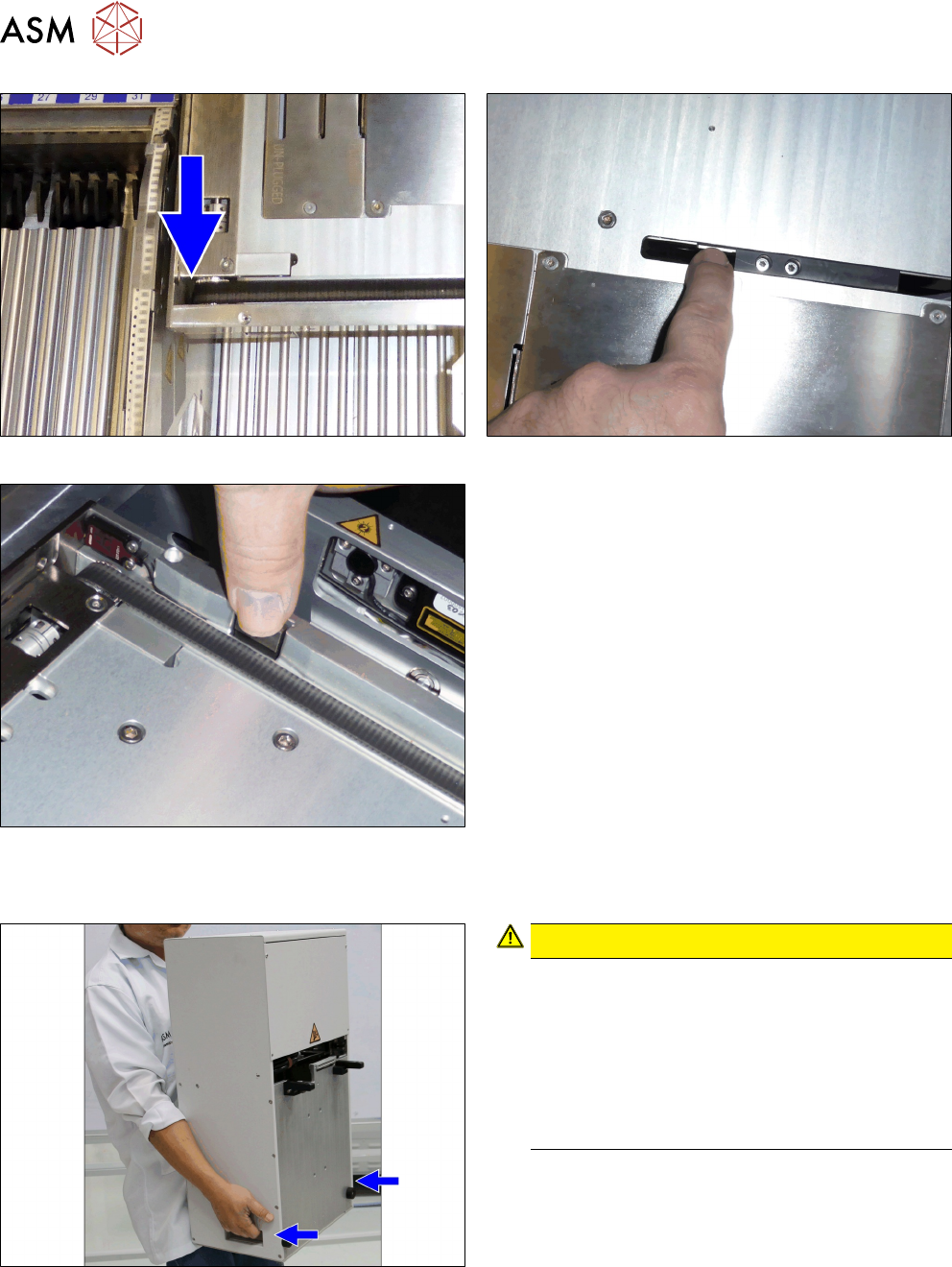
Fig.4: Conveyor belt rollers Fig.5: Pusher
Fig.6: Side tray clamp
1.1.5 Safety Instructions for Transporting the Module
Fig.7: Holding the tower
CAUTION!
Tower weight
The weight of the tower (26.3 kg) could cause in-
juries if the module is not handled correctly.
Always hold the tower with two hands. Use the
handles on the sides of the tower.
Tower and conveyor must be transported separ-
ately. Mishandling will cause damage to the
SIPLACE JTF‑ML2.
.
1 Introduction
1.2 Preparatory Work...
Service Manual SIPLACE JTF-ML2 08/2017 11
1.2 Preparatory Work...
Purpose and scope
Before performing any preventive maintenance work, conversion work or service work, a procedure
of locking and tagging must be followed and warning signs must be attached if not stated other-
wise. If it is not necessary to switch off the machine, it is explicitly mentioned.
The procedure, when followed correctly, eliminates the possibility of an employee being injured.
NOTICE
Additional safety measures
This procedure represents the minimum lock out and tag out requirements for the machine
during preventive maintenance work and service work. Any additional safeguards needed
to complete work safely can be specified by facilities supervision, the safety officer, the
safety committee and the health department.
Description
Whenever it becomes necessary to isolate, control and release energy, the following procedure is
to be followed.
► Notify all affected employees.
► Switch off the machine and all additional devices. Carry out all normal stopping procedures:
ð Press the STOP button.
ð Shut down the station computer.
ð Switch off the machine using the main switch.
► Isolate the machine from all its energy sources:
ð Shut off the compressed air supply.
ð Shut off the main power supply.
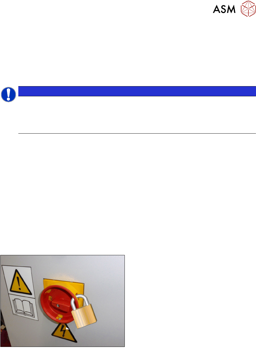
► Lock out the machine.
ð Attach a lock wherever possible:
Fig.8: Attaching a padlock to the main power switch
Secure Main Switch
► Secure the main switch with a padlock.
► Alternative: Attaching warning signs:
If a machine can be locked, it must be.
However, there are situations where energy isolating devices cannot accommodate locks. In
these cases, the energy isolating devices must be tagged to warn employees that the
machine is de-energized for servicing. The tag or label must be securely fastened, it must be
placed in a position visible to all and it may only be removed by the person who attached it.