00198377-01_SM_JTF-ML2_en.pdf - 第131页
5 Electrics 5.6 Replacing the Light Aperture Service Manual SIPLACE JTF-ML2 08/2017 131 5.6 Replacing the Light Aperture Parts, Equipment and Tools ● Standard tools ● Light aperture [03113302-xx] Removal ► Switch off the…
5 Electrics
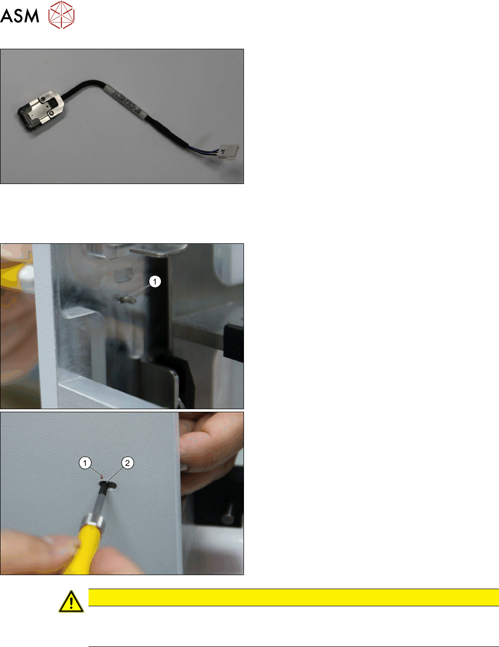
5.5 Replacing the Beam Sensor Receiver Cable
130 Service Manual SIPLACE JTF-ML2 08/2017
► Remove the Cable, through beam sensor recei-
ver [03146663-xx].
Installation
► Follow the removal instructions in reverse order for installation. Also observe the following in-
structions:
► Fix the screw [03042525-xx] (2) at the marked
spot (1).
CAUTION
Danger of tray crash
Wrong positioning will result in tray crash. Do a functional test on the gap sensor before re-
lease for production. Readjust if necessary.
5 Electrics
5.6 Replacing the Light Aperture
Service Manual SIPLACE JTF-ML2 08/2017 131
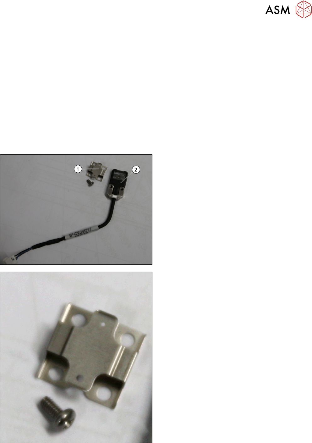
5.6 Replacing the Light Aperture
Parts, Equipment and Tools
●
Standard tools
●
Light aperture [03113302-xx]
Removal
► Switch off the machine, disconnect it from the power supply and secure it to prevent
unauthorized reactivation. Observe the instructions in section 1.2 "Preparatory Work..." [}11].
► Remove the tower from the machine ( see 2.1.2 "Removing Tower from Machine" [}21]).
► Remove the top cover (see 2.1.3 "Removing Tower Top Cover" [}25]).
► Remove the side cover (see 2.1.4 "Removing Side Cover" [}27]).
► Remove the Cable, through beam sensor receiver [03146663-xx] (see 5.5 "Replacing the
Beam Sensor Receiver Cable" [}129]).
► Remove the Light aperture [03113302-xx] (1)
from the beam sensor receiver [03146663-xx] (2).
Light aperture [03113302-xx]
5 Electrics
5.7 Replacing the PCBA JTF-ML2 Control Board
132 Service Manual SIPLACE JTF-ML2 08/2017
Installation
► Follow the removal instructions in reverse order for installation.
NOTICE
Correct orientation
One hole is smaller than the other. Make sure to install the correct orientation.
See also
2 Replacing the Light Aperture [}131]
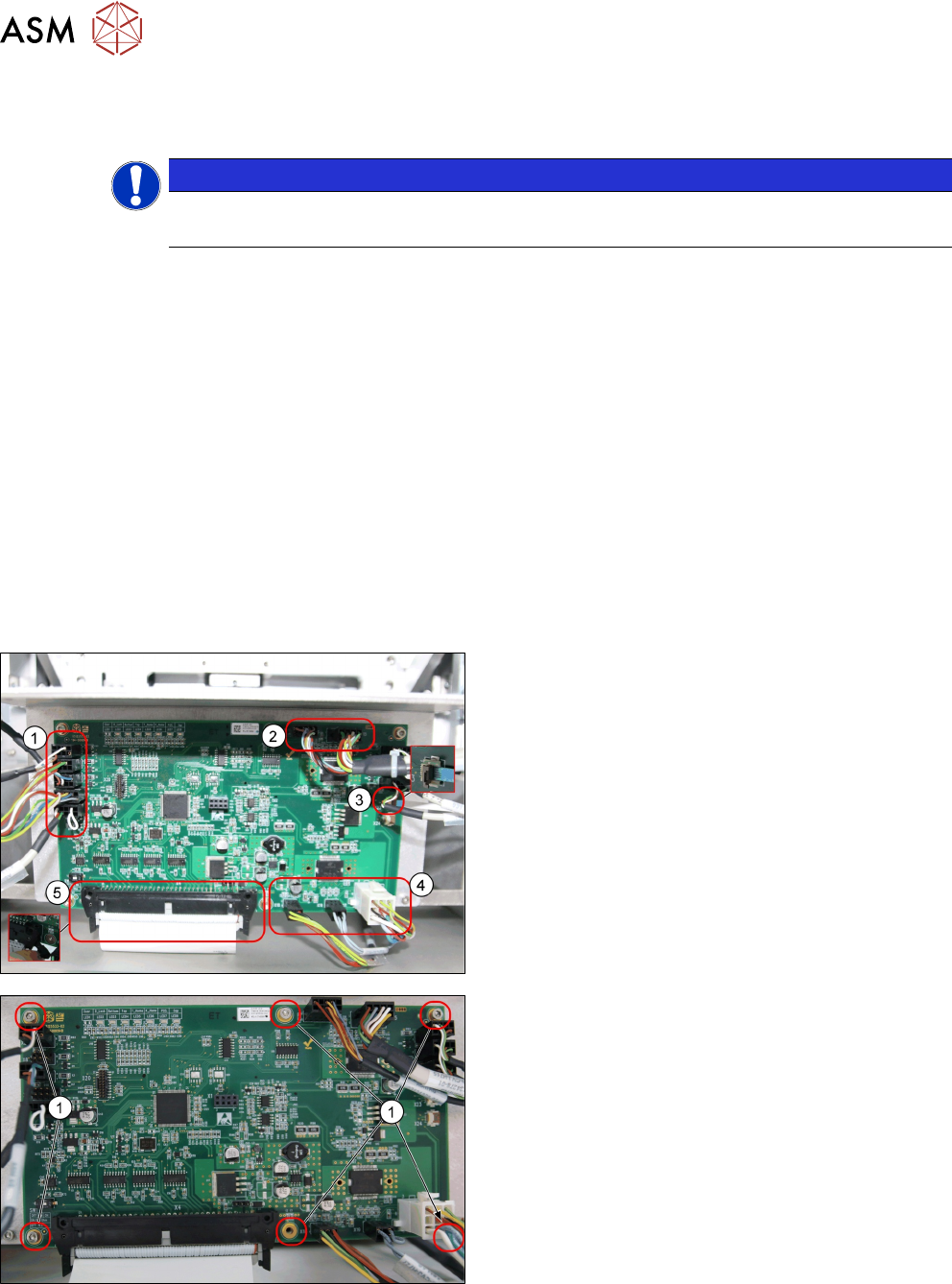
5.7 Replacing the PCBA JTF-ML2 Control Board
Parts, Equipment and Tools
●
Standard tools
●
PCBA Tesla control board [03125534-xx]
Removal
► Switch off the machine, disconnect it from the power supply and secure it to prevent
unauthorized reactivation. Observe the instructions in section 1.2 "Preparatory Work..." [}11].
► Remove the tower from the machine (see 2.1.2 "Removing Tower from Machine" [}21]).
► Remove the top cover (see 2.1.3 "Removing Tower Top Cover" [}25]).
► Remove all cables from the PCBA, JFT-ML2 con-
trol board [03125534-xx].
1. X22; X8; X7; X6; X5
2. X16; X15
3. X23
4. X18; X19; X17
5. X4
► Remove the six screws ISO 4762 - M 3 x 6-A2-70
[03042541-xx] (1).