00198377-01_SM_JTF-ML2_en.pdf - 第68页
3 Tower Mechanics 3.13 Removing the Dual Kicker and Dismantling Parts 68 Service Manual SIPLACE JTF-ML2 08/2017 ► Fasten the screws (1) and mount the hard stop. NOTICE Bumper During tray kick out process ensure the troll…
3 Tower Mechanics
3.13 Removing the Dual Kicker and Dismantling Parts
Service Manual SIPLACE JTF-ML2 08/2017 67
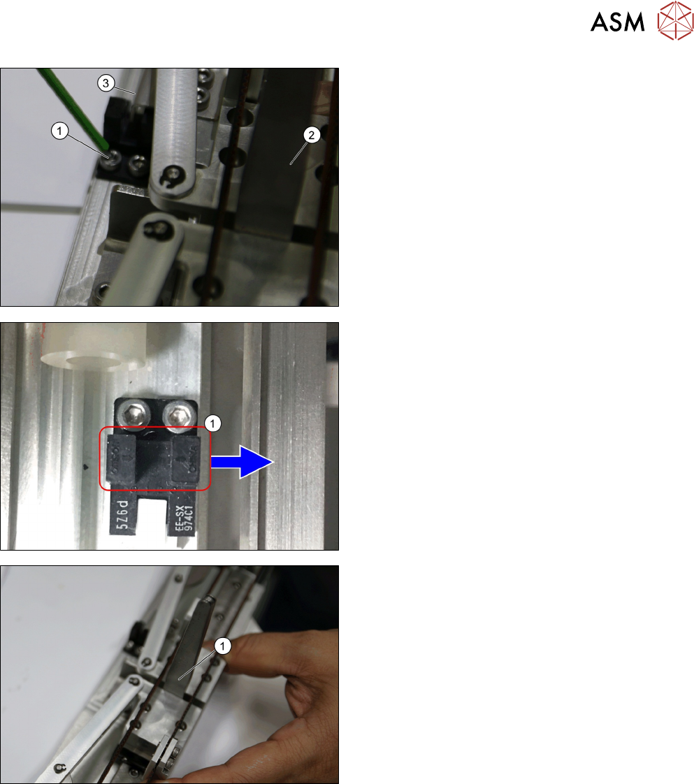
► Mount the sensor and adjust it such that the ar-
rows on the sensor align with the edge of the
sensor plate (3), while ensuring the 4.5mm gap is
maintained (using the feeler gauge (2)).
► Fasten the two screws (1) of the home sensor.
► Make sure the arrows (1) on the sensor points in-
side towards the tower.
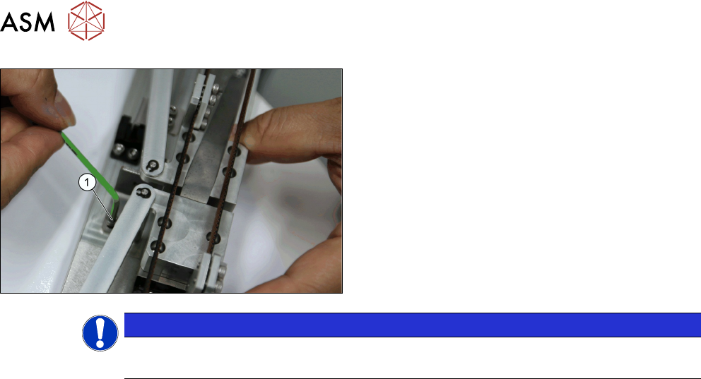
Clamping is needed here before measuring to verify
distance between bumper and sensor arrow indicated
(1).
► Ensure there is a 3.5mm gap. Mount the ureth-
ane bumper (hard stop) such that it just touches
the trolley block
3 Tower Mechanics
3.13 Removing the Dual Kicker and Dismantling Parts
68 Service Manual SIPLACE JTF-ML2 08/2017
► Fasten the screws (1) and mount the hard stop.
NOTICE
Bumper
During tray kick out process ensure the trolley block does not touch the urethane bumper.
4 Conveyor Mechanics
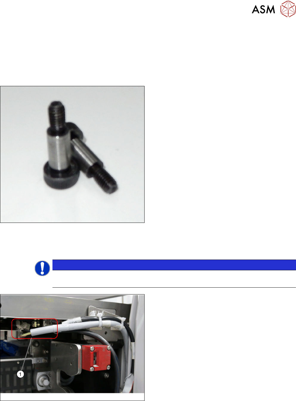
4.1 Replacing the Fitting Screw [03005652-xx]
Service Manual SIPLACE JTF-ML2 08/2017 69
4 Conveyor Mechanics
4.1 Replacing the Fitting Screw [03005652-xx]
Parts, Equipment and Tools
●
Standard tools
●
Fitting screw ISO 7379 - 10 x 25-12.9 [03005652-
xx]
Removal
► Switch off the machine, disconnect it from the power supply and secure it to prevent
unauthorized reactivation. Observe the instructions in section 1.2 "Preparatory Work..." [}11].
NOTICE
Cassettes
Make sure all cassettes are removed from the tower before powering down.
► Unplug the cables from the connectors X2.COTI1
and X4.COTI1 in the conveyor base of the
SIPLACE JTF-ML2 (1).