00198377-01_SM_JTF-ML2_en.pdf - 第86页
4 Conveyor Mechanics 4.4 Replacing the Driven Pulley 86 Service Manual SIPLACE JTF-ML2 08/2017 Conveyor roller assembly [03129007-xx] Installation ► Follow the removal instructions in reverse order for installation. ► Te…
4 Conveyor Mechanics
4.3 Replacing the Conveyor Roller Assembly
Service Manual SIPLACE JTF-ML2 08/2017 85
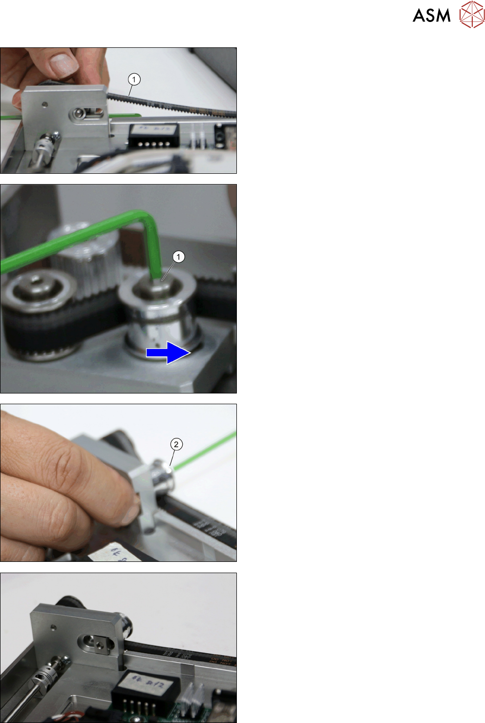
► Once the roller adjuster is loose the belt (1) can
be removed.
► Remove socket head shoulder screw M4x5x16
(1).
► Remove Conveyor roller assembly [03129007-xx]
(2).
Socket head shoulder screw M4x5x16 from back side.
4 Conveyor Mechanics
4.4 Replacing the Driven Pulley
86 Service Manual SIPLACE JTF-ML2 08/2017
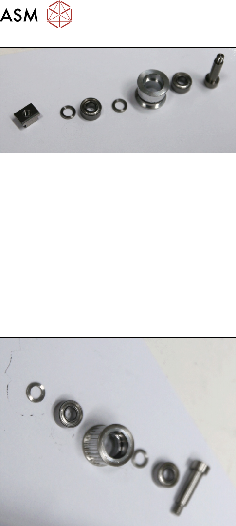
Conveyor roller assembly [03129007-xx]
Installation
► Follow the removal instructions in reverse order for installation.
► Test the belt tension with the belt tension measuring device. It should be at 70 +/- 5 Hz.
See also
2 Removing Conveyor from Machine [}17]
4.4 Replacing the Driven Pulley
Parts, Equipment and Tools
●
Standard tools
●
Belt tension measuring device [00326015‑xx]
●
Driven pulley assembly [03133576-xx]
4 Conveyor Mechanics
4.4 Replacing the Driven Pulley
Service Manual SIPLACE JTF-ML2 08/2017 87
Removal
► Switch off the machine, disconnect it from the power supply and secure it to prevent
unauthorized reactivation. Observe the instructions in section 1.2 "Preparatory Work..." [}11].
► Remove the conveyor (See Removing SIPLACE JTF-ML2 Conveyor from Machine).
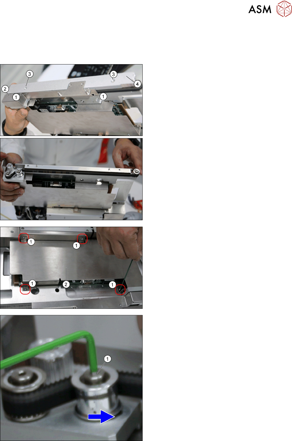
► Remove the two screws DIN EN ISO 7380-M3 x
5-A2-70 [03045193-xx] (1).
► Remove the Left belt cover [03145447-xx] (2).
► Remove the two screws ISO 4762 - M 4 x 8-
A2-70 [03042551 –xx] (3).
► Remove the right Rail [03147568-xx] (4).
► Remove the four screws DIN EN ISO 7380-M3 x
5-A2-70 [03045193-xx] (1).
► Remove the PCB cover [03128922-xx] (2).
► Loosen socket head shoulder screw M4x5x16
[03145465-xx] (1), to right to loosen belt.