00198377-01_SM_JTF-ML2_en.pdf - 第58页
3 Tower Mechanics 3.13 Removing the Dual Kicker and Dismantling Parts 58 Service Manual SIPLACE JTF-ML2 08/2017 Dual Kicker [03155270-xx] ► To do further work on the Dual Kicker [03155270-xx] place it on a stable surface…
3 Tower Mechanics
3.13 Removing the Dual Kicker and Dismantling Parts
Service Manual SIPLACE JTF-ML2 08/2017 57
3.13 Removing the Dual Kicker and Dismantling Parts
Parts, Equipment and Tools
●
Standard tools
●
Dual kicker [03155270-xx]
Removal
► Switch off the machine, disconnect it from the power supply and secure it to prevent
unauthorized reactivation. Observe the instructions in section 1.2 "Preparatory Work..." [}11].
► Remove the top cover (see 2.1.3 "Removing Tower Top Cover" [}25]).
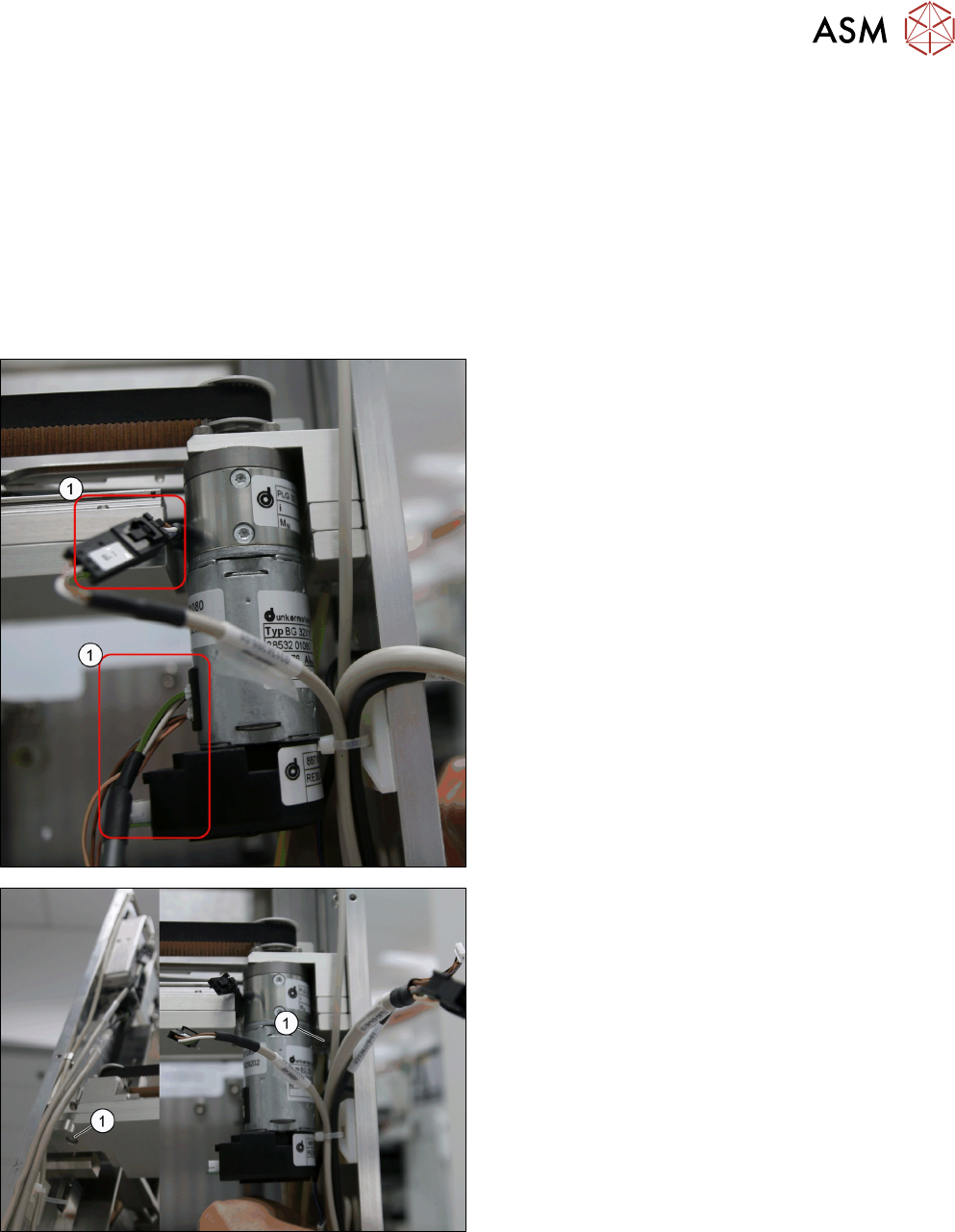
► Remove the sensor cable from X18 (1) from the
BG32x10 BLDC motor w/ gearbox encoder
[03127773-xx].
► Remove the two screws ISO 4762 - M 4 x 12-
A2-70 [03042553-xx] (1) from the Belt kicker
base 2 [03153357-xx].
► Remove the Dual Kicker [03155270-xx] from the
tower.
3 Tower Mechanics
3.13 Removing the Dual Kicker and Dismantling Parts
58 Service Manual SIPLACE JTF-ML2 08/2017
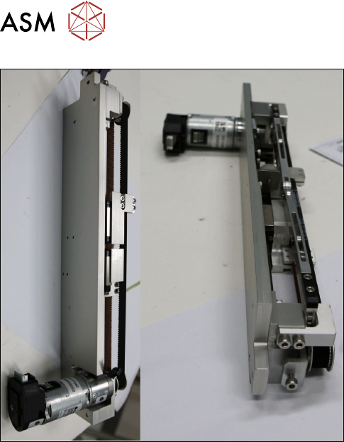
Dual Kicker [03155270-xx]
► To do further work on the Dual Kicker [03155270-xx] place it on a stable surface like a work
bench.
Installation
► Follow the removal instructions in reverse order for installation.
See also
2 Replacing the Kicker Tip Test [}59]
2 Replacing the Driven Pulley [}60]
2 Replacing the Dual Kicker Timing Belt [}62]
2 Replacing the Motor Sub-Assembly [}63]
3 Tower Mechanics
3.13 Removing the Dual Kicker and Dismantling Parts
Service Manual SIPLACE JTF-ML2 08/2017 59
3.13.1 Replacing the Kicker Tip Test
Parts, Equipment and Tools
●
Standard tools
●
Kicker tip test v3 [03124708-xx]
Removal
► Switch off the machine, disconnect it from the power supply and secure it to prevent
unauthorized reactivation. Observe the instructions in section 1.2 "Preparatory Work..." [}11].
► Remove the top cover (see 2.1.3 "Removing Tower Top Cover" [}25]).
► Remove the Dual Kicker [03155270-xx] (see 3.13 "Removing the Dual Kicker and Dismantling
Parts" [}57])
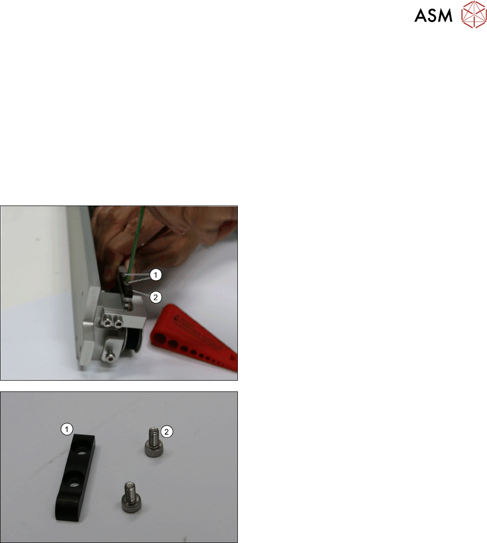
► Remove the two screws DIN EN ISO 7380-M3 x
6-A2-70 [03045194-xx] (1).
► Remove Kicker tip test v3 [03124708-xx] (2).
1. Kicker tip test v3 [03124708-xx]
2. Two screws DIN EN ISO 7380-M3 x 6-A2-70
[03045194-xx]
Installation
► Follow the removal instructions in reverse order for installation.