00198377-01_SM_JTF-ML2_en.pdf - 第135页
5 Electrics 5.9 Replacing the PCBA Conveyor Drive Board Service Manual SIPLACE JTF-ML2 08/2017 135 5.9 Replacing the PCBA Conveyor Drive Board Parts, Equipment and Tools ● Standard tools ● PCBA, conveyor drive board [031…
5 Electrics
5.8 Replacing the Reflective Sensor Cable
134 Service Manual SIPLACE JTF-ML2 08/2017
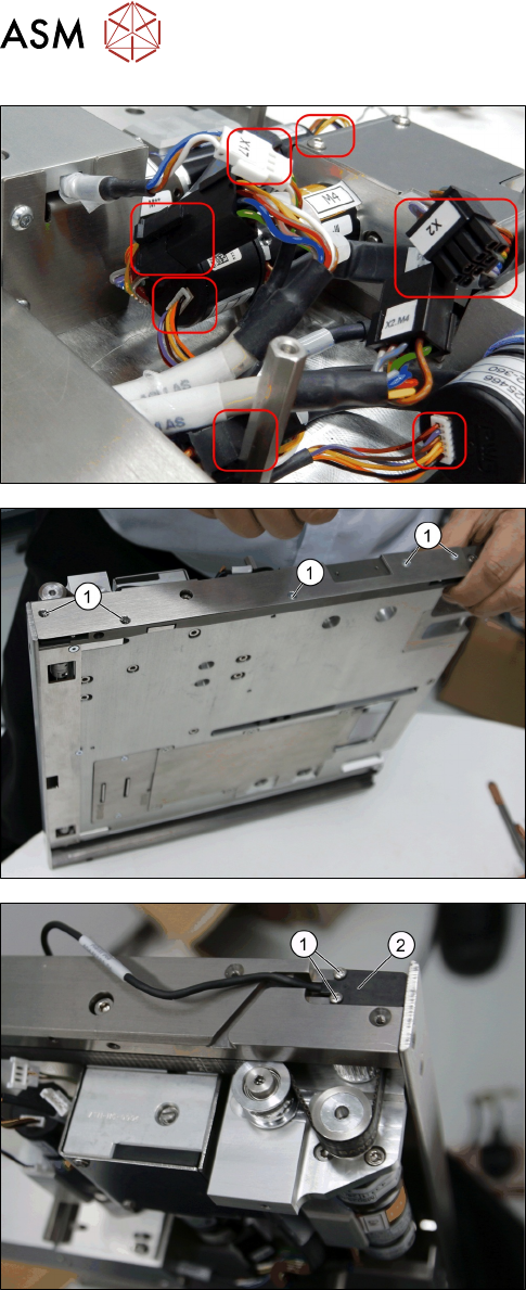
► Remove all the cables necessary.
► Remove the five screws ISO 7380-2 M 3 x 6-
A2-70 [03099571-xx] (1).
► Remove the two screws ISO 7045 - M2 x 4-
A2-50-H [03010197-xx] on the Cable, reflective
sensor, common [03146661-xx].
► Remove the Cable, reflective sensor, common
[03146661-xx].
Installation
► Follow the removal instructions in reverse order for installation.
5 Electrics
5.9 Replacing the PCBA Conveyor Drive Board
Service Manual SIPLACE JTF-ML2 08/2017 135
5.9 Replacing the PCBA Conveyor Drive Board
Parts, Equipment and Tools
●
Standard tools
●
PCBA, conveyor drive board [03128812-xx]
Removal
► Switch off the machine, disconnect it from the power supply and secure it to prevent
unauthorized reactivation. Observe the instructions in section 1.2 "Preparatory Work..." [}11].
► Remove the conveyor from the machine (see 2.1.1 "Removing Conveyor from Ma-
chine" [}17]).
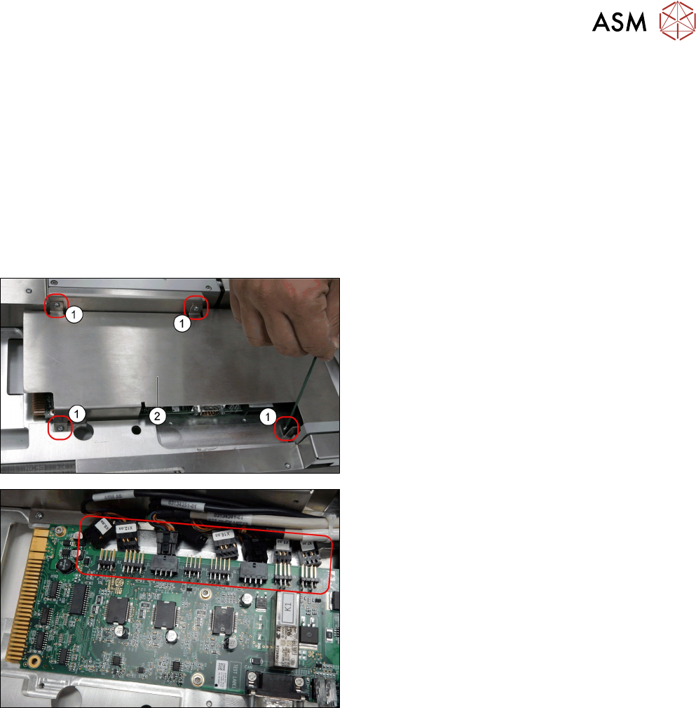
► Remove the four screws DIN EN ISO 7380-M3 x
5-A2-70 [03045193-xx].
► Remove the PCB cover [03128922-xx]
► Remove all cables from the PCBA, conveyor
drive board [03128812-xx].
5 Electrics
5.9 Replacing the PCBA Conveyor Drive Board
136 Service Manual SIPLACE JTF-ML2 08/2017
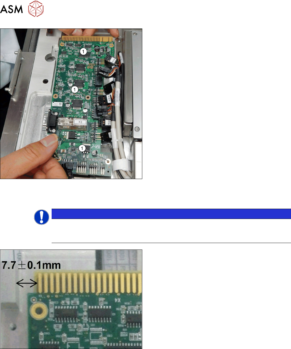
► Remove the six screws DIN EN ISO 7380-M3 x
5-A2-70 [03045193-xx] (1).
► Remove the PCBA, conveyor drive board
[03128812-xx].
Installation
► Follow the removal instructions in reverse order for installation.
NOTICE
Crushing of cables
When assembling, test the position by plugging and unplugging it into the tower. The cables
should not be to tight to fit the board back in.
The distance between the PCBA Conveyor Drive
Board and the Conveyor has to be 7.7 +/- 0.1mm.