00198377-01_SM_JTF-ML2_en.pdf - 第105页
4 Conveyor Mechanics 4.7 Replacing the Pusher Unit and Parts Service Manual SIPLACE JTF-ML2 08/2017 105 4.7.4 Replacing the LM Guide Parts, Equipment and Tools ● Standard tools ● LM Guide W12x6 L175 [03127165-xx] Removal…
4 Conveyor Mechanics
4.7 Replacing the Pusher Unit and Parts
104 Service Manual SIPLACE JTF-ML2 08/2017
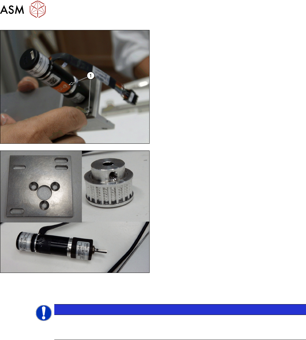
► Loosen the two screws ISO 4762 - M 3 x 6-A2-70
[03042541-xx] (1) on the Pusher 22 motor mount-
ing [03147369-xx] to release tension on the
Toothed belt Synchroflex 6+-0.1 S3M/459
[03146204-xx].
► Remove the two screws ISO 4762 - M 3 x 6-
A2-70 [03042541-xx] (1).
► Remove the Motor w/ pulley f. pusher [03147371-
xx].
Installation
► Follow the removal instructions in reverse order for installation.
NOTICE
Motor shaft
Take care to align the flat side of the motor shaft to be perpendicular to the insertion direc-
tion of the set screw during assembly.
4 Conveyor Mechanics
4.7 Replacing the Pusher Unit and Parts
Service Manual SIPLACE JTF-ML2 08/2017 105
4.7.4 Replacing the LM Guide
Parts, Equipment and Tools
●
Standard tools
●
LM Guide W12x6 L175 [03127165-xx]
Removal
► Switch off the machine, disconnect it from the power supply and secure it to prevent
unauthorized reactivation. Observe the instructions in section 1.2 "Preparatory Work..." [}11].
► Remove the conveyor from the machine (see 2.1.1 "Removing Conveyor from Ma-
chine" [}17]).
► Remove the Pusher from the conveyor (see 4.7 "Replacing the Pusher Unit and Parts" [}95]).
► Remove the belt from the Pusher (see 4.7.1 "Replacing the Toothed Belt Synchroflex" [}97]).
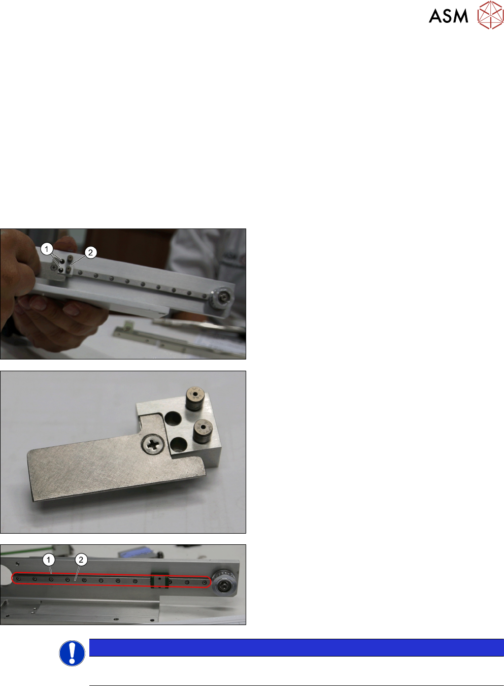
► Remove the two screws ISO 4762 - M 2 x 6-
A2-70 [03042525-xx] (1) from the Pusher trans-
mission block update [03145807-xx] (2).
Pusher transmission block update [03145807-xx]
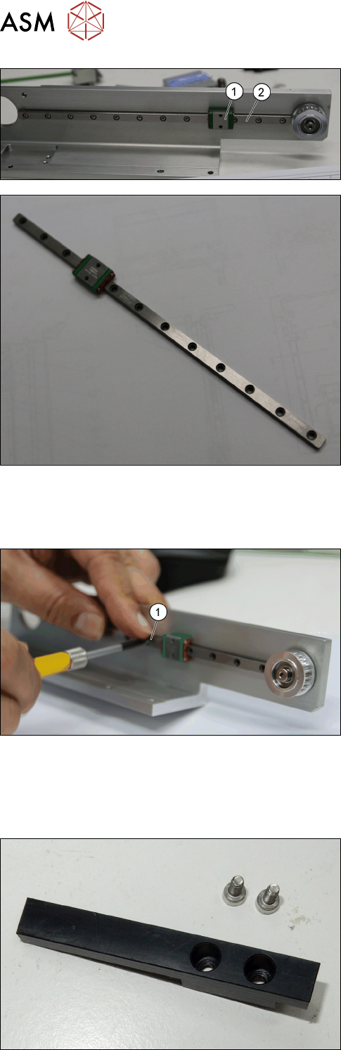
► Remove the 12 screws PACK-SMIB2.0-6
(Misumi) [03155269-xx] (1) from the LM Guide
W12x6 L175 [03127165-xx] (2).
NOTICE
Special low head screw
Make sure not to loose the screws PACK-SMIB2.0-6 (Misumi) [03155269-xx].
4 Conveyor Mechanics
4.7 Replacing the Pusher Unit and Parts
106 Service Manual SIPLACE JTF-ML2 08/2017
► Remove the LM Guide W12x6 L175 [03127165-
xx] (2).
► Leave the trolley (1) on the LM Guide W12x6
L175 [03127165-xx] (2).
LM Guide W12x6 L175 [03127165-xx]
Installation
► Follow the removal instructions in reverse order for installation. Also observe the following in-
structions:
► Start to fasten the screws ISO 4762 - M 2 x 6-
A2-70 [03042525-xx] (1) from the middle screw.
► Continue to fasten the screws left and right al-
ternating to the outside to ensure the guide rail is
assembled properly..
4.7.5 Replacing the Pusher Tip
Parts, Equipment and Tools
●
Standard tools
●
Pusher tip [03132851-xx] (with two screws ISO
4762 - M 3 x 6-A2-70 [03042541-xx])