00198377-01_SM_JTF-ML2_en.pdf - 第76页
4 Conveyor Mechanics 4.2 Removing the Conveyor Driver Unit and its Parts as Preparatory Steps 76 Service Manual SIPLACE JTF-ML2 08/2017 4.2.2 Replacing the BLDC Motor and Conveyor Drive Pulley Parts, Equipment and Tools …
4 Conveyor Mechanics
4.2 Removing the Conveyor Driver Unit and its Parts as Preparatory Steps
Service Manual SIPLACE JTF-ML2 08/2017 75
4.2.1 Replacing the Driving Pulley
Parts, Equipment and Tools
●
Standard tools
●
Driving pulley S2MZ26 [03128931-xx]
Removal
► Remove the conveyor (See Removing SIPLACE JTF-ML2 Conveyor from Machine).
► Follow the instructions to get to Conveyor driver unit [03132255--xx] parts ( See 4.2 "Remov-
ing the Conveyor Driver Unit and its Parts as Preparatory Steps" [}72]).
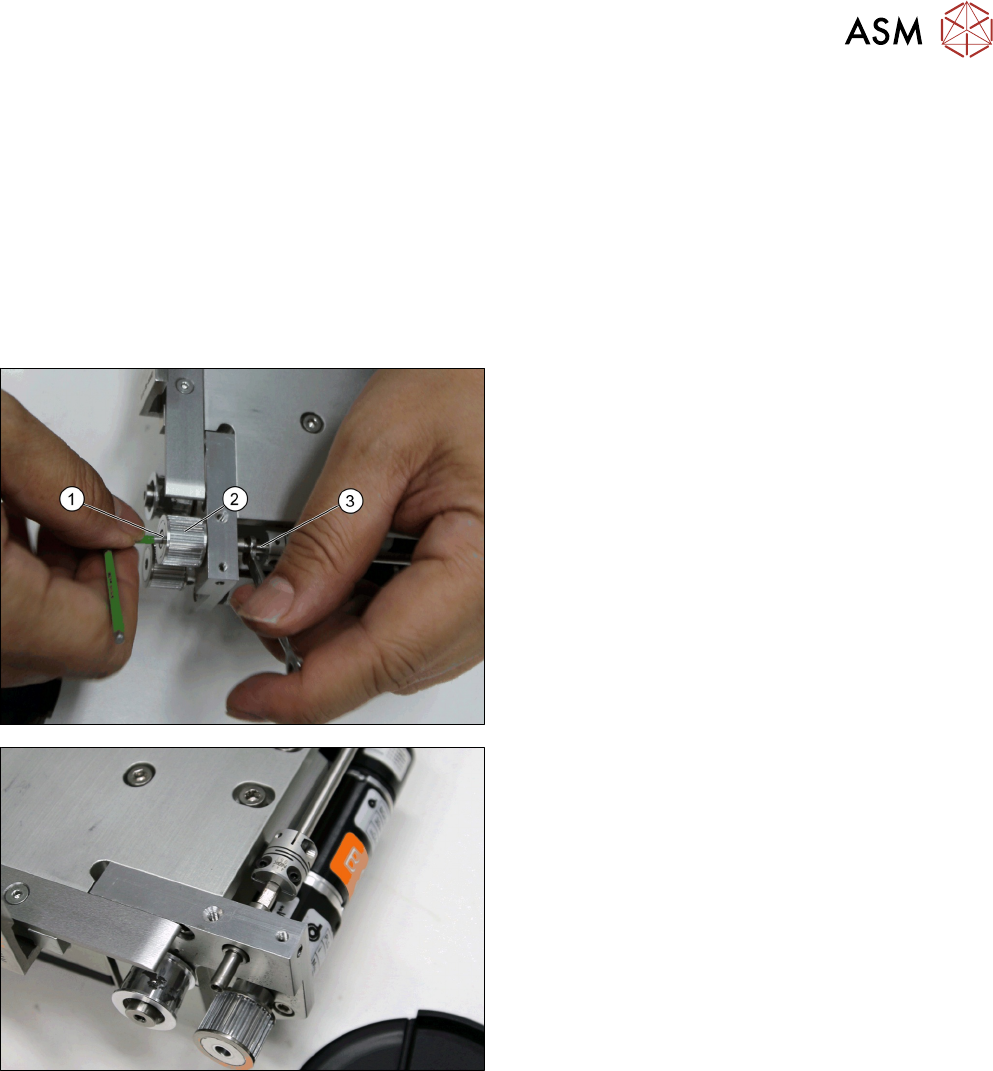
► Remove the screw ISO 4762 - M 3 x 6-A2-70
[03042541-xx] (1) while holding the conveyor
shaft (3) with a screw wrench.
► Remove the Driving pulley S2MZ26 [03128931-
xx] (2).
Driving pulley S2MZ26 [03128931-xx] removed.
Installation
► Follow the removal instructions in reverse order for installation.
4 Conveyor Mechanics
4.2 Removing the Conveyor Driver Unit and its Parts as Preparatory Steps
76 Service Manual SIPLACE JTF-ML2 08/2017
4.2.2 Replacing the BLDC Motor and Conveyor Drive Pulley
Parts, Equipment and Tools
●
Standard tools
●
Motor assembly, BLDC motor with encoder, gear-
box [03146371-xx]
●
Conveyor drive pulley with set screw [03156654-
xx]
Removal
► Remove the conveyor (See 2.1.1 "Removing Conveyor from Machine" [}17]).
► Follow the instructions to get to Conveyor driver unit [03132255--xx] parts (See 4.2 "Removing
the Conveyor Driver Unit and its Parts as Preparatory Steps" [}72]).
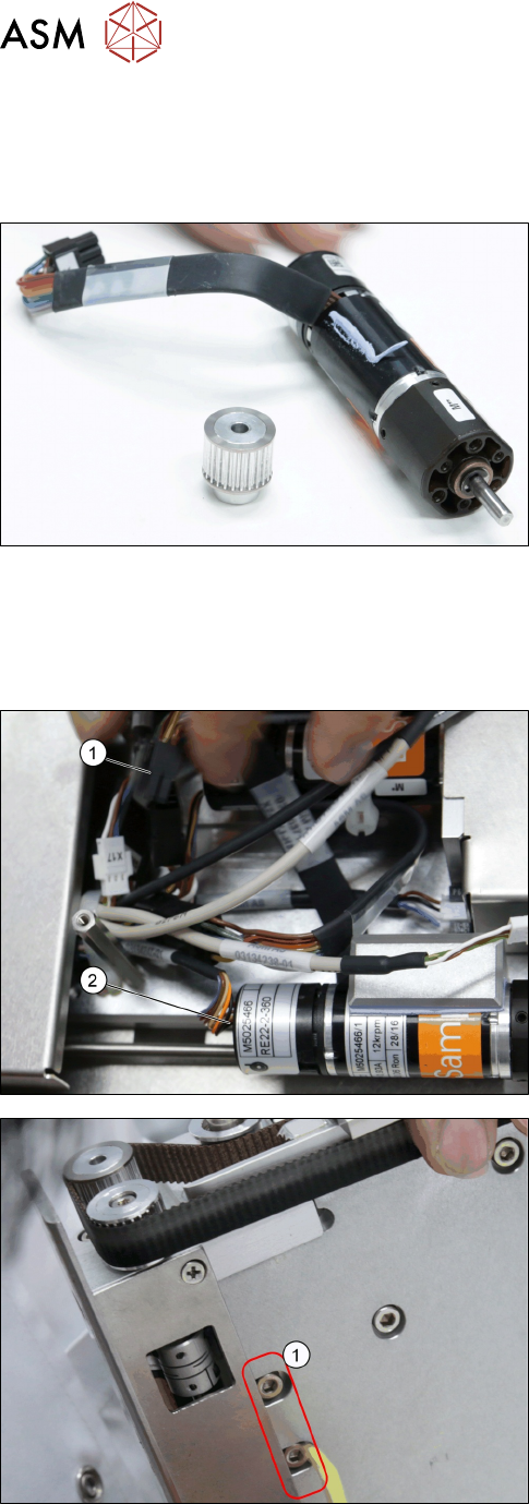
► Remove connector from the motor (2).
► Disconnect the cable (1).
► Remove the two screws ISO 4762 - M 4 x 8-
A2-70 [03042551-xx] (2).
4 Conveyor Mechanics
4.2 Removing the Conveyor Driver Unit and its Parts as Preparatory Steps
Service Manual SIPLACE JTF-ML2 08/2017 77
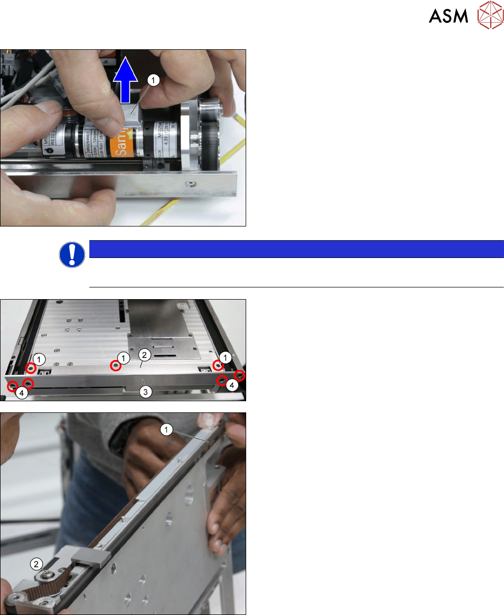
► Remove the Conveyor motor heat transfer block
A [03148017-xx] (1).
NOTICE
Heat transfer interface sheet
Take care not to tear the heat transfer interface sheet.
► Remove the two screws ISO 10642 - M3x6-
A2-70 [03082814-xx] (1).
► Remove the Conveyor top cover [03147570-xx]
(2).
► Remove the two screws ISO 10642 - M3x6-
A2-70 [03082814-xx] (4).
► Remove the Stopper plate [03132873-xx] (3).
► Loosen the tension pulley (2).
► Carefully remove the Toothed belt 10+-0.1
S2M/726 [03130743-xx] (1).