00198377-01_SM_JTF-ML2_en.pdf - 第66页
3 Tower Mechanics 3.13 Removing the Dual Kicker and Dismantling Parts 66 Service Manual SIPLACE JTF-ML2 08/2017 3.13.5 Final Steps Before Remounting the Kicker NOTICE Belt tension The belt tension will change when the ki…
3 Tower Mechanics
3.13 Removing the Dual Kicker and Dismantling Parts
Service Manual SIPLACE JTF-ML2 08/2017 65
Motor Sub- Assembly [03156525-xx]
Installation
► Follow the removal instructions in reverse order for installation. Also observe the following
steps:
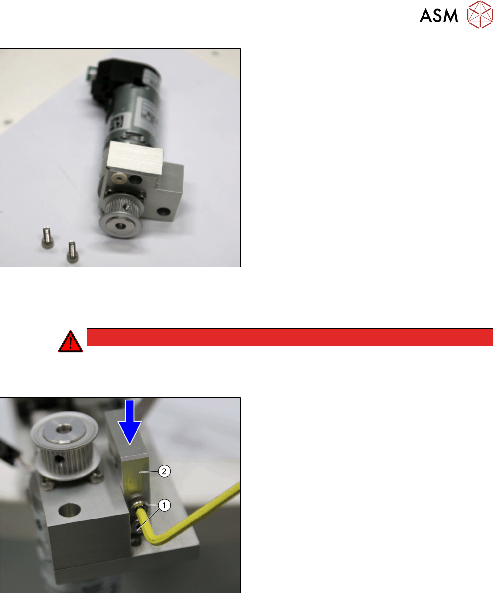
DANGER
Danger of a crash
If there is a gap between the bushing holder and the belt kicker mounting, the bushing
holder could move.
► While fixing the two screws ISO 4762 - M 4 x 12-
A2-70 [03042553-xx] (1), press the Bushing
Holder top v2 [03155358-xx] (2) down.
3 Tower Mechanics
3.13 Removing the Dual Kicker and Dismantling Parts
66 Service Manual SIPLACE JTF-ML2 08/2017
3.13.5 Final Steps Before Remounting the Kicker
NOTICE
Belt tension
The belt tension will change when the kicker is in operation and when the clamp is moun-
ted.
NOTICE
Belt tension
The belt tension is higher after the Pusher levers v2 L=65 [03155364-xx] are mounted, es-
pecially when they are moved to the middle.
CAUTION
Danger of Crash
Adjusted to be in the same position away from the lifter when the kicker is retracted at
home position.
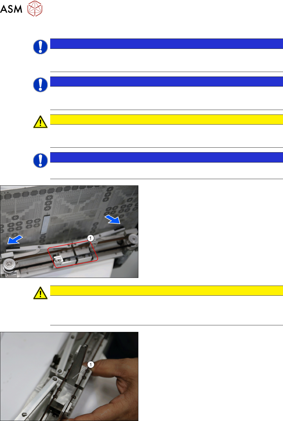
NOTICE
Danger of Grinding
If the belt is not centered exact on the pulleys it grinds on the trolleys (1).
► After reassembling make sure, that the position
of the kicker tippers are symmetrical.
► Test the synchronized movement to ensure sym-
metrical position with a plate as shown.
► Loosen or tighten the screws on the pusher
levers to adjust the pusher levers.
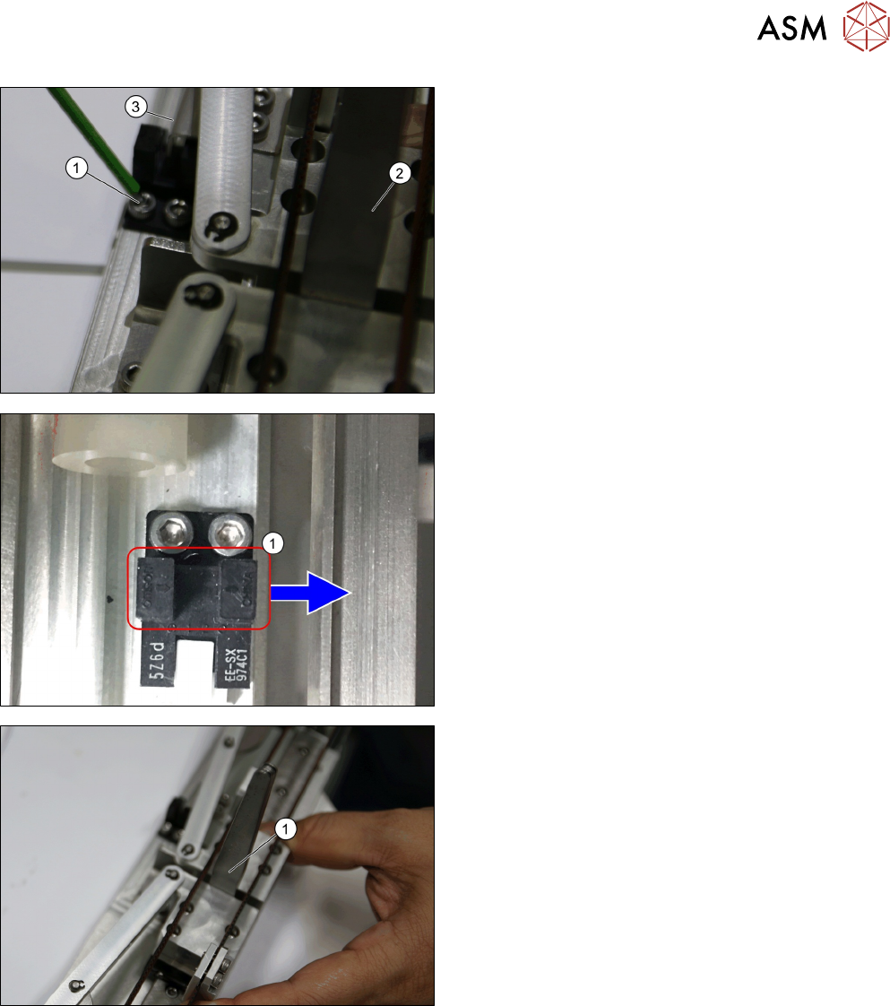
CAUTION
Tray not parallel to cassette
If not synchronized the pusher levers will cause the tray to be kicked out not parallel to the
cassette. Backlash can happen if the belt tension is wrong, or the below adjustment is not
done properly.
► Ensure that there is a 4.5mm (feeler gauge (1))
gap between the trolley block.
3 Tower Mechanics
3.13 Removing the Dual Kicker and Dismantling Parts
Service Manual SIPLACE JTF-ML2 08/2017 67
► Mount the sensor and adjust it such that the ar-
rows on the sensor align with the edge of the
sensor plate (3), while ensuring the 4.5mm gap is
maintained (using the feeler gauge (2)).
► Fasten the two screws (1) of the home sensor.
► Make sure the arrows (1) on the sensor points in-
side towards the tower.
Clamping is needed here before measuring to verify
distance between bumper and sensor arrow indicated
(1).
► Ensure there is a 3.5mm gap. Mount the ureth-
ane bumper (hard stop) such that it just touches
the trolley block