SIPLACE Line Computer UNIX.pdf - 第172页
5 Product / Component User Manual Line Computer UNIX 5.1 Component Editor Software V ersion 502.xx 10/2000 Issue 170 I t I I 5.1.2 Main Window of Component Edi tor The areas of the mai n window a nd their func tions are …
User Manual Line Computer UNIX 5 Product / Component
Software Version 502.xx 10/2000 Issue 5.1 Component Editor
169
I
t I I
5 Product / Component
5.1 Component Editor
The Component Editor enables the user to completely describe the components in terms of their electrical
characteristics. In the Editor, the component type (e.g. diode), its electrical characteristics and its type of
processing (e.g. gluing, placing) are defined. Moreover, the component is assigned a package form no. in
accordance with its particular package design.
5.1.1 Starting the Component Editor
-
In the "programming mode" the Component Editor is activated by clicking on the Component icon on
the desktop or via the Data Manager (see
chapt. 4).
- If the LC program was installed for the "control mode", the Component Editor can be started via the
"PRODUCT" menu on the desktop, or via the Data Manager.
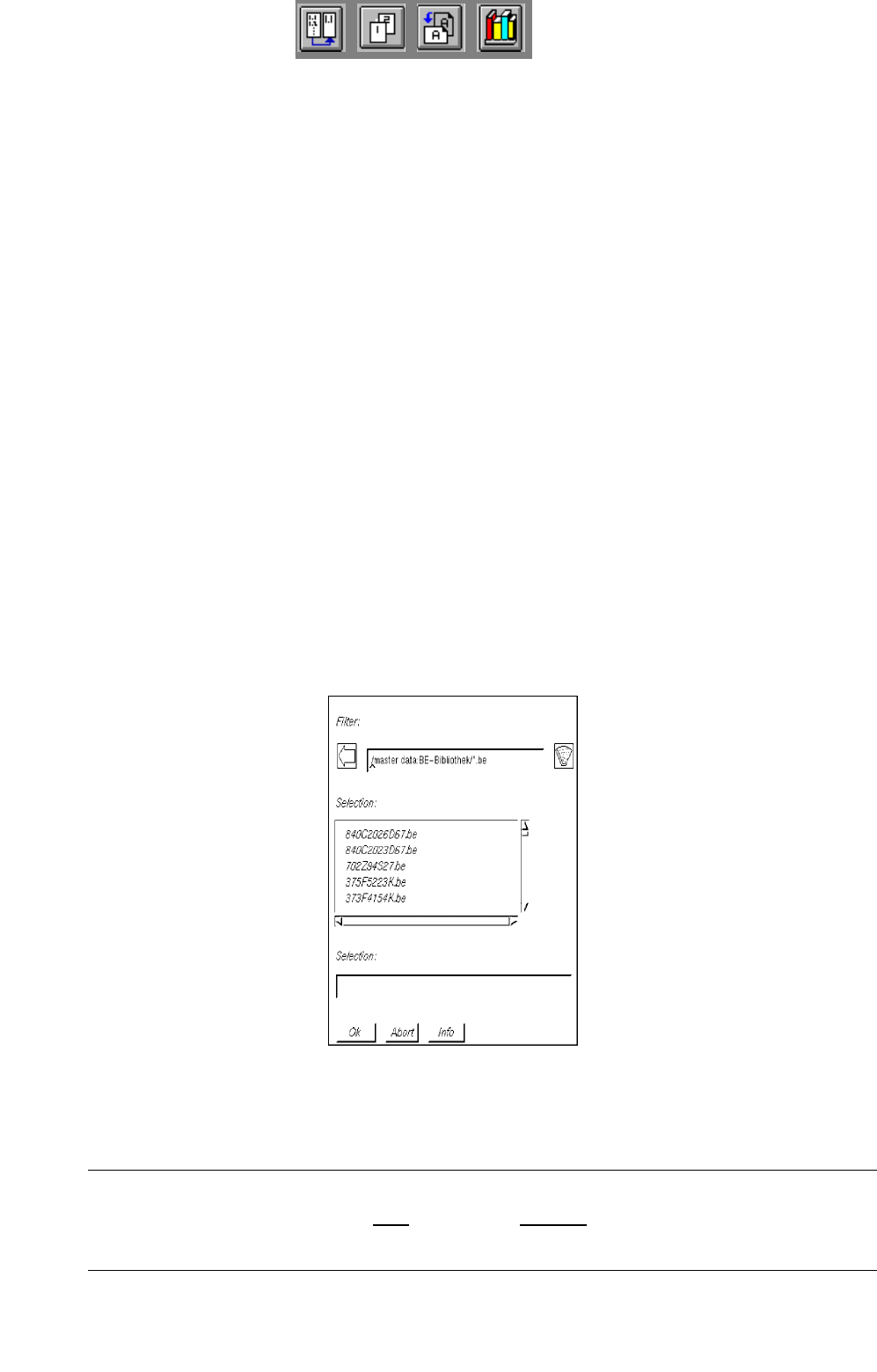
● Click on the Component icon on the desktop (or the "Component Editor" option on the
"PRODUCT" menu). The FSB containing the files of all previously defined components is opened.
● Select component "xx.be" by double-clicking, or enter new name on the keyboard and confirm
with OK.
The main window containing the Component Editor (see
Fig. 5.1.1) is opened.
NOTE
The component name may comprise max.
20 characters including the suffix ".be". Some characters
must not be used for the name, see chapt. 2, section 2.3 in this connection.
5 Product / Component User Manual Line Computer UNIX
5.1 Component Editor Software Version 502.xx 10/2000 Issue
170
I
t I I
5.1.2 Main Window of Component Editor
The areas of the main window and their functions are explained in the following.
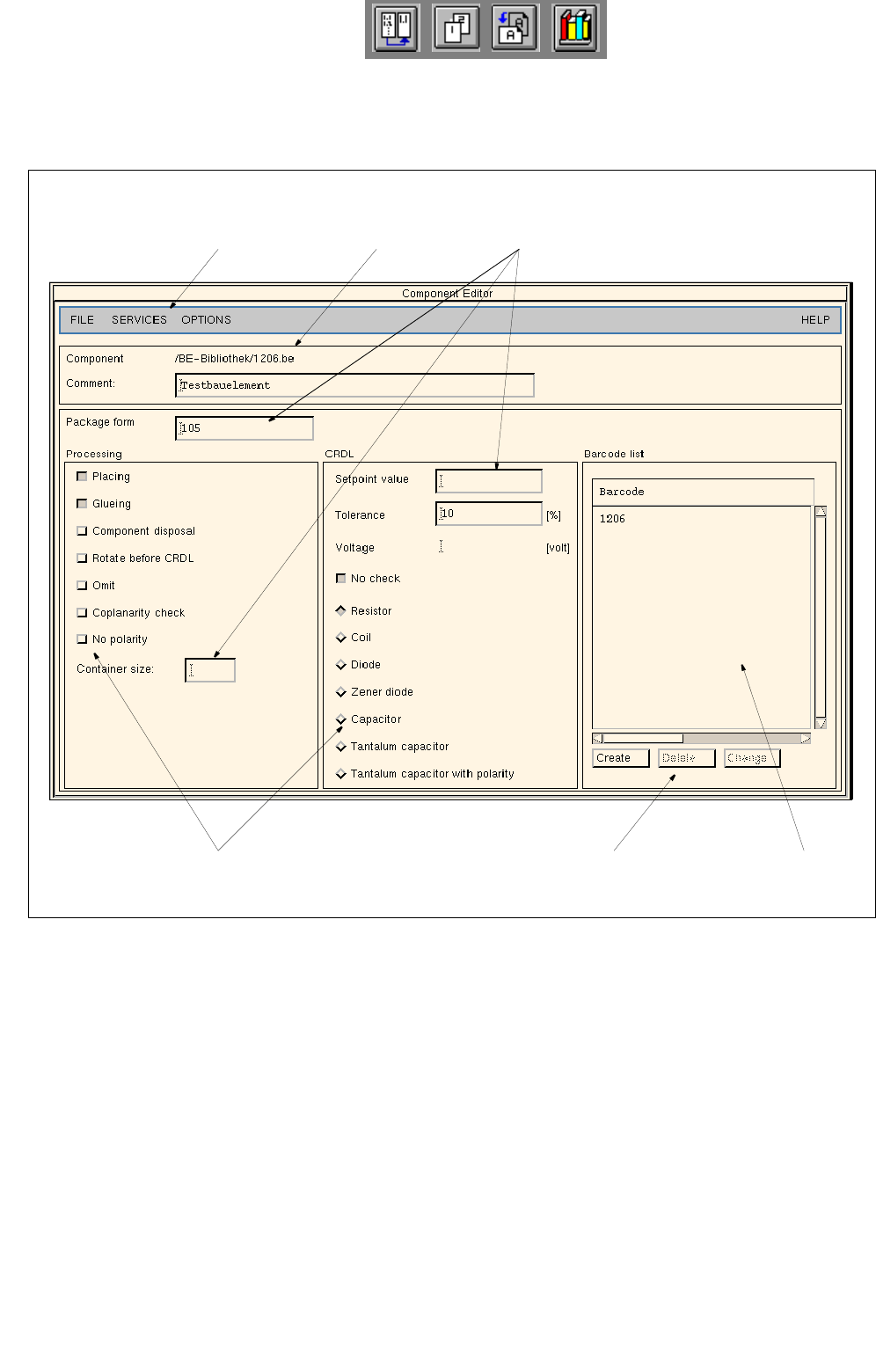
Fig. 5.1.1 Main Window "Component Editor"
The main window is subdivided as follows:
- Menu bar
- Title bar
- Editing fields
- Selection fields
- Command area
- Display area
menu bar
title bar
editing fields
selection fields command area display area

User Manual Line Computer UNIX 5 Product / Component
Software Version 502.xx 10/2000 Issue 5.1 Component Editor
171
I
t I I
Menu bar
The menu bar contains the "FILE", "SERVICES", "OPTIONS" and "HELP" menus.
A complete description of the "SERVICES" menu is contained in section 5.1.2.1.
NOTE
Since the functions and operation of the "FILE", "OPTIONS" and "HELP" menus are similar to those in
other application programs of the line computer, they are described comprehensively in chapt. 2.
Title bar
The title bar displays the directory in which the selected component (or the component file) is contained and
the name of the component.
Editing fields (see
section 5.1.2.3)
In the editing fields below the title bar an optional comment and the package form no. corresponding
to the particular component type can be entered.
The container size is to be entered in the associated editing box in the selection box "Processing".
The setpoint (nominal) value, the tolerance and the voltage value (only in the case of tantalum capacitors) of
the component for the CRDL test are entered in the appropriate editing fields in the selection field "CRDL".
Selection fields (see
section 5.1.2.2)
In the selection field "Processing" (left portion of the main window) the type of processing for the particular
component is defined.
The selection field "CRDL" (right portion of the main window) serves to define the type of a particular component
to (e.g. component type "diode"). By selecting the component type the corresponding CRDL test will be
performed for the particular component (e.g. a voltage check in the case of a diode).
Command area (see
section 5.1.2.4)
When activated, the commands in this area can be used to create a total of 6 barcodes for the current component,
or to delete or change already existing barcodes.
Display Area
All barcodes created for the current component are displayed in the view area.