SIPLACE Line Computer UNIX.pdf - 第279页
User Manual Line Computer UNIX 9 Production Tools / Feeders Software Version 502.xx 10/2000 Issue 9. 1 Feeder Editor 277 I t I I 9 Production T ools / Feeders 9.1 Feed er Editor The fol lowing al locatio ns are defi ned …
8 Product / PCB User Manual Line Computer UNIX
8.1 PCB Editor Software Version 502.xx 10/2000 Issue
276
I
t I I
Procedures to be followed for the searching and replacing of character strings
● In the setting area, activate the button with the desired search direction by clicking on it (see Fig.
8.1.12
).
● Enter the character string to be searched for in the "Find what:" editing field.
● Enter new character string in the "Replace with:" editing field if the character string entered in the
"Find what:" editing field is to be replaced.
● Click on the Search button in the command area.
The first occurrence of the character strings searched for appears darkened in the editing area of
the Placement Position Editor window. Clicking on the button again, causes the subsequent
occurrence of the character string within the given search area to be highlighted.
● Click on the Replace button in the command area.
The highlighted character string is replaced with the character string entered in the "Replace
with:" editing field and subsequently the next character string found in the search area is automa-
tically highlighted.
Or else:
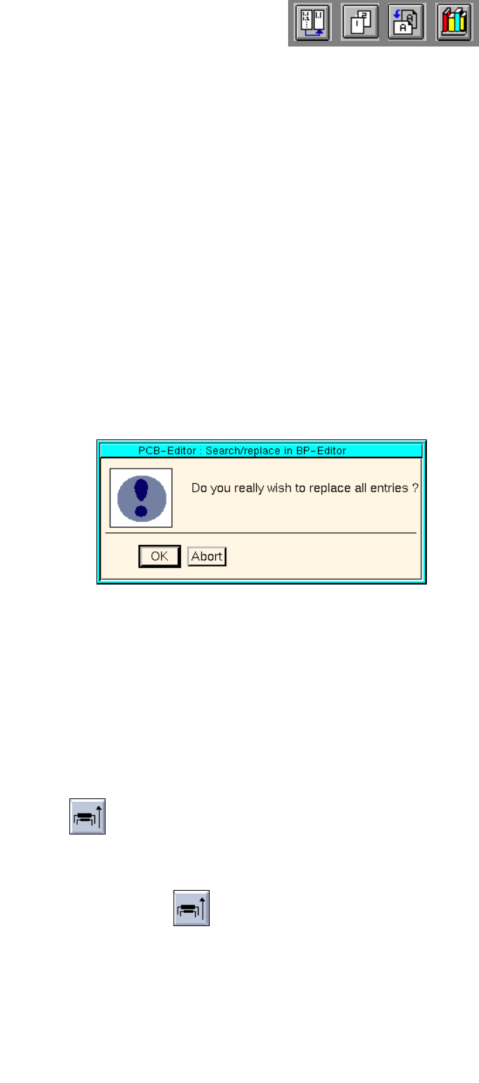
● Click on the Replace all button in the command area.
The dialog box below is displayed.
● Click on OK.
All identical character strings occurring in the search area are replaced with the character string
entered in the "Replace with:" editing field. Subsequently, an information box is displayed infor-
ming you that the end of the file has been reached.
● If necessary, activate the button for the opposite search direction to carry out additional replace-
ments.
● When the searching/replacing operation is completed, click on Cancel to terminate the search
window. The search window is closed.
- Sort
This function serves to sort the placement position data in accordance with the level numbers, if
available.
● Click on the icon in the command area.
The PP data is sorted by the level numbers. Sorting is performed in ascending order (see
Fig.
8.1.11
).

User Manual Line Computer UNIX 9 Production Tools / Feeders
Software Version 502.xx 10/2000 Issue 9.1 Feeder Editor
277
I
t I I
9 Production Tools / Feeders
9.1 Feeder Editor
The following allocations are defined by means of the Feeder Editor:
The feeding equipment (feeder/waffle pack tray) to be used to supply a specific package form or component
and the type of machine on which the feeder is to be set up. It is possible to specify a different feeder or
waffle pack tray for each machine type.
NOTE
Predefined feeders or "customer-specific types" can be selected for the allocations. The so-called
"customer-specific types" are feeder or waffle pack tray types created by the user with the aid of the
Feeder Editor whose data deviate from the standard values (see section 9.1.4).
The allocations specified in the Feeder Editor are stored in the ".ri" set-up info file in the Master data/RI-
Bibliothek. For optimization purposes it is mandatory that the ".ri"-file be always
available. The optimization
function evaluates the data from the ".ri"-file and determines where a given package form or component is
to be set up. When so doing, allocations of components have a higher weighting than allocations of package
forms, and special allocations (e.g. to a customer-specific type) carry a higher weight than general
allocations.
9 Production Tools / Feeders User Manual Line Computer UNIX
9.1 Feeder Editor Software Version 502.xx 10/2000 Issue
278
I
t I I
9.1.1 Allocation Possibilities
The various possibilities of allocations are described in the following:
For each package form, and thus each component, contained in the master data it is necessary that its set-up
be defined at one time, i.e. an allocation must be defined between component/package form -> feeder ->
machine type.
NOTE
To limit the amount of work involved, allocations should preferably be made for package forms, as different
components frequently have the same package form.
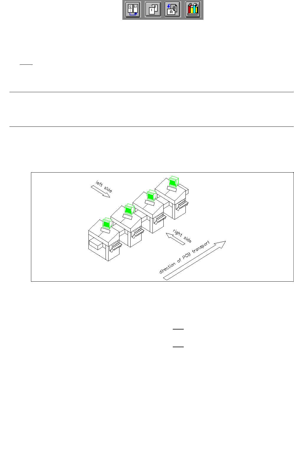
- The component/package form can be set up on one side of a line only.
The distinction between the machine sides is accomplished by the designations "Left side" and "Right
side" (as seen in the direction of travel).
Fig. 9.1.1 Direction of travel, left side/right side
The definitions are determined according to the following types of allocation:
Left side ---> The component/package form may only be set up on the feeder parts of the
left side of the line.
right side ---> The component/package form may only be set up on the feeder parts of the
right side of the line.
- The component/package form can only be set up on a specific machine type.
- The feeders can be assigned correction values for the pick-up position of a component
(x,y,z and α) as well as the vibration time.