SIPLACE Line Computer UNIX.pdf - 第384页
12 Production Tools / Station and Line Con figuration User Manual Line Compu ter UNIX 12.2 Line Editor Software Version 5 02.xx 10 /2000 Issue 382 I t I I ● Read the v erification q ueries in the dia log box and c onfirm…
User Manual Line Computer UNIX 12 Production Tools / Station and Line Configuration
Software Version 502.xx 10/2000 Issue 12.2 Line Editor
381
I
t I I
Saving the configuration:
● On the menu bar select the option File --> Save.
The cluster configuration will be saved.
● On the menu bar select the option File --> Exit.
The "Cluster configuration" window closes.
In the display area of the desktop the defined cluster limits are identified by red lines in the graphi-
cal display of the relevant line configuration (see
chapt. 3, Fig. 3.1.5) .
12.2.4 Selecting the Production Line
The line computer can only control one line at a time. This overall line is referred to as production line. If several
lines are configured, the possibility exists to switch to a different production line. To do this, all stations must
be reset, the line computer must be shut down and restarted.
To select a new production line:
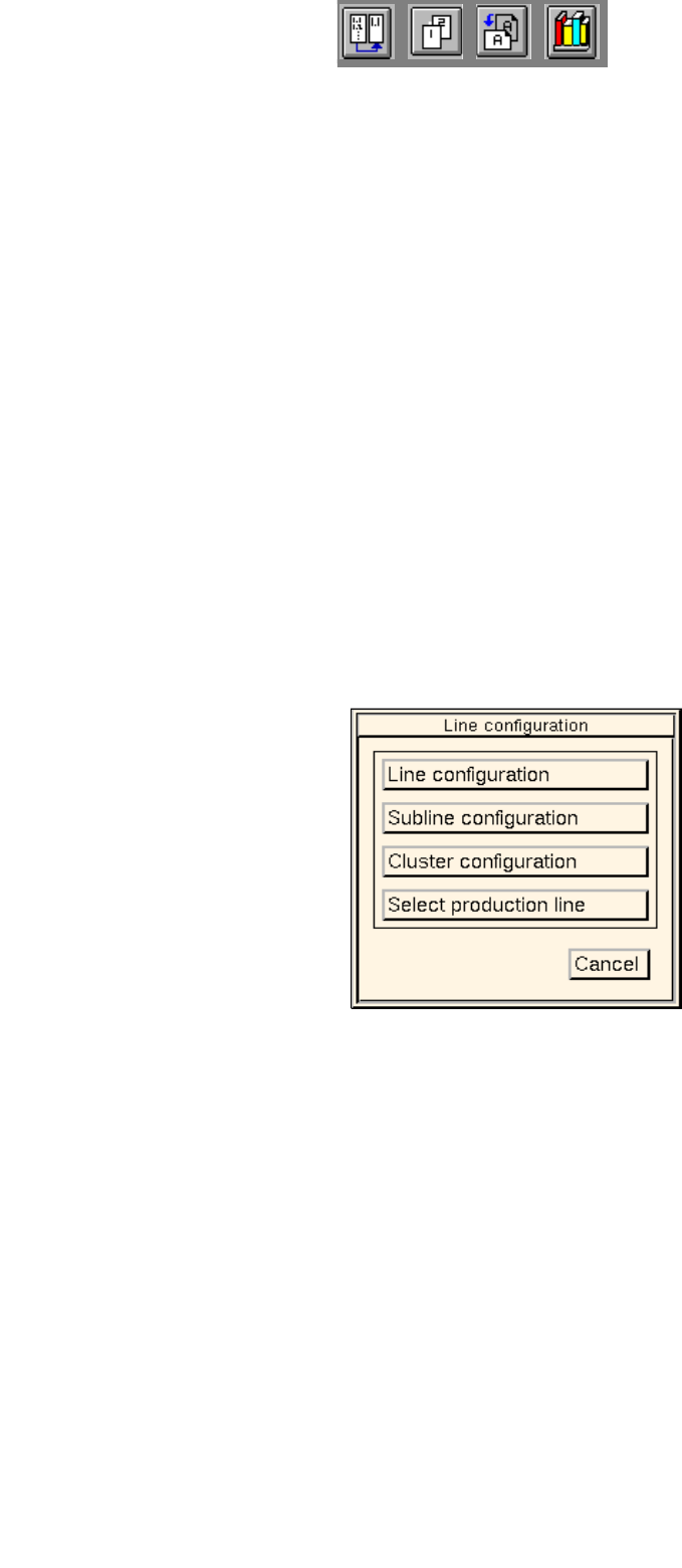
● On the menu bar on the desktop click on SERVICES --> Line configuration.
The
"Line configuration" selection window opens.
● Click on the Select production line button.
The FSB containing the "Master data: Anlagen" directory opens.
All configured lines are displayed in the selection list.
● Select the desired line "xx.ak" by double-clicking.
The FSB closes and the following dialog box opens:
12 Production Tools / Station and Line Configuration User Manual Line Computer UNIX
12.2 Line Editor Software Version 502.xx 10/2000 Issue
382
I
t I I
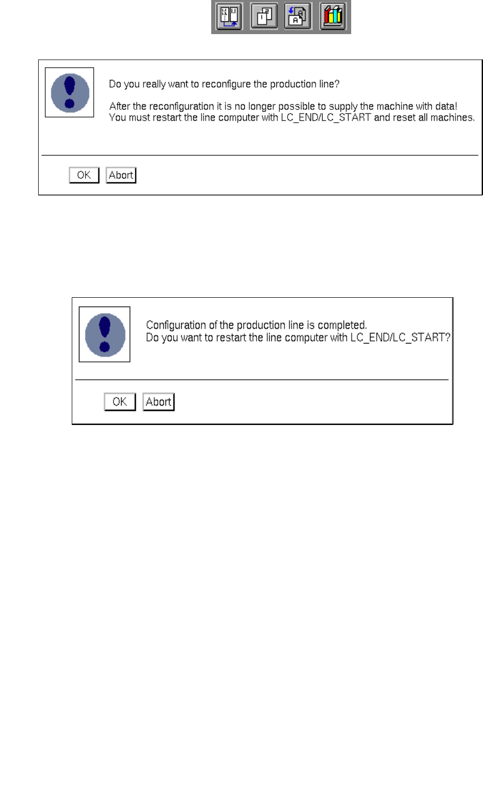
● Read the verification queries in the dialog box and confirm the new configuration of the produc-
tion line by selecting OK. The selected line is now configured as the production line.
Subsequently, the following dialog box is displayed:
● Turn off all stations.
● Confirm the dialog box with OK.
The line computer session is automatically terminated and a new session is started with the
selected line as the production line.
● Turn the stations back on once the "desktop" is displayed on the screen.

User Manual Line Computer UNIX 13 Production Tools / Set-Up
Software Version 502.xx 10/2000 Issue 13.1 Set-Up Editor (Feeder Part and WPC/MTC Editors)
383
I
t I I
13 Production Tools / Set-Up
13.1 Set-Up Editor (Feeder Part and WPC/MTC Editors)
The Set-Up Editor enables the manual creation of new set-ups and the manual modification of existing set-ups.
When so doing, the feeders and waffle pack trays contained in the feeder list are allocated to the individual
feeder parts. The components are allocated to the individual divisions of the feeders and waffle pack trays.
Predefined allocations of components and package forms are accessed by means of the RI-file option. This
option permits an effective and error-free creation of set-ups and its use should be given preference to other
methods.
The "Packaging box" option permits you to define waffle pack trays and to enter correction values for the pick-
up position of the component in the tray division, as well as the vibration time.
The "Nozzle Changer" option permits you to configure the nozzle changer.
The options list contains all possible options available for a given line. The waffle pack changer (WPC), the
matrix tray changer (MTC) and the component disposal conveyor may also be allocated via the options list in
the Feeder Part Editor, if required.
The Set-Up Editor is to be called up separately for the feeder parts of the stations and the Waffle Pack Changer
or Matrix Tray Changer. The two editors - Feeder Part Editor and WPC/MTC Editor - are identical as far as their
functions are concerned, they do, however, differ in the layout of their display area. They are described
separately in the following sections of this manual.
A separate section is dedicated to the description of the Virtual Level of an HS180.
13.1.1 Feeder Part Editor
The Feeder Part Editor is designed for the creation of set-ups on placement stations. It must be called up
separately for each individual station.
13.1.1.1 Starting the Feeder Part Editor
The Feeder Part Editor is invoked from the desktop. The feeder parts of the individual stations are identified in
green color on the graphical display of the line configuration. Clicking on these areas highlighted in green causes
the Feeder Part Editor to be opened (see Fig. 13.1.1).