SIPLACE Line Computer UNIX.pdf - 第432页
14 Control / Control Modules User Manual Line Computer UNIX 14.2 Job Control Software Version 502.xx 10 /2000 Issue 430 I t I I - Results... The "Res ults..." men u optio n can only be select ed if a jo b was p…
User Manual Line Computer UNIX 14 Control / Control Modules
Software Version 502.xx 10/2000 Issue 14.2 Job Control
429
I
t I I
Or:
● Activate the (Merge all) icon.
The dialog window closes and all jobs are added to the current job list or lot file.
●
NOTE
If jobs have been selected that already exist in the job list or lot file, the message "Error during
merging the lot file! Job name used more than once" appears.
If individual
jobs from a lot file are inserted into the current job list, these jobs are no longer contained
in the lot file.
If all
jobs from a lot file are inserted into the current job list or lot file, the lot file is automatically
deleted.
- Barcode type allocation list...
(Description see section 14.2.3.3)
- Basic optimization data...
(Description see section 14.2.3.4)
- Optimization dialog...
This menu option enables the optimization dialog (user interface of Set-Up Optimization to be opened.
● Click on SERVICES --> Optimization Dialog...
The main window of the Optimization Dialog is opened (see
chapt. 11).
- Line Control...
The Line Control main window can be opened using this menu item.
● Click on SERVICES --> Line Control...
The main window of Line Control is opened (see
section 14.3. Fig. 14.3.1).
- Setup Modification Generator...
The "Setup Modification Generator..." menu item can only be selected if a job is selected from the job
list beforehand. The applicable setup is then displayed for the selected job in the main window of the
Setup Modification Generator.
● Click on SERVICES --> Setup modification generator...
The main window of the Setup modification generator opens (see
section 14.5. Fig. 14.5.2).
The setup for the selected job is displayed in the display area.
If two jobs were selected from the job list, the difference between the setups of the two jobs is dis-
played.

14 Control / Control Modules User Manual Line Computer UNIX
14.2 Job Control Software Version 502.xx 10/2000 Issue
430
I
t I I
- Results...
The "Results..." menu option can only be selected if a job was previously selected from the job list.
The results of the producibility check can be displayed for the selected job.
● Deactivate all buttons in the command area.
● Select the desired job from the job list.
● Select SERVICES --> Results...
The window containing the results of the producibility check is opened (see
chapt. 11, Fig. 11.4.5).
The window displays the cycle time, the number of placement positions, the number of cycles and
the performance of the individual placement heads, the individual stations and the entire line.
- Error messages...
All error messages and warnings that occurred during a producibility check are stored in the "all.error"
file. The contents of the "all.error" file can be displayed by following the procedures described below.
● Deactivate all icons in the command area.
● Select faulty job by double-clicking.
(A faulty job is identified by an "F" preceding its name).
The main window of File Display is opened (see
chapt. 4). It contains all error messages and
warnings that occurred during the producibility check.
Or:
● Select faulty job by clicking on it once.
● Click on SERVICES --> Error messages...
The main window of File Display containing the contents of "all.error" file is opened.
User Manual Line Computer UNIX 14 Control / Control Modules
Software Version 502.xx 10/2000 Issue 14.2 Job Control
431
I
t I I
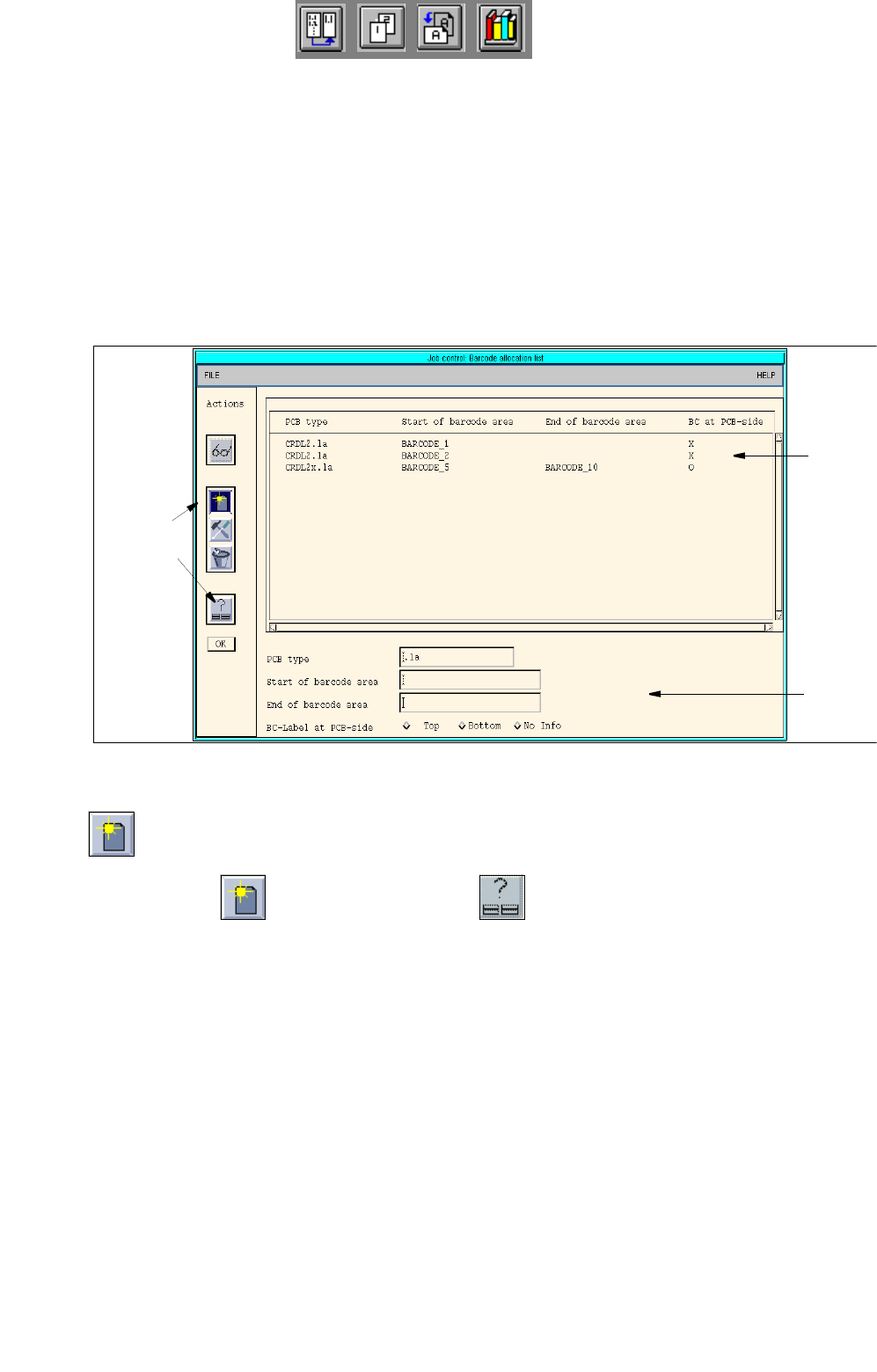
14.2.3.3 Editing Barcode Type Allocation List
When using PCB barcodes, the appropriate barcodes must be allocated to the PCBs. This is accomplished by
means of the "Barcode type allocation list..." menu option.
● Click on SERVICES --> Barcode type allocation list... (with the job list loaded).
The window containing the barcode type allocation list opens (see
Fig. 14.2.3).
Here, given barcode ranges (Start barcode --> End barcode) can be allocated to the PCB types,
or existing allocations can be edited. An additional setting allows the side of the PCB to be speci-
fied from which the barcode is to be read in (depending on the installation position of the barcode
reader at the station).
Fig. 14.2.3 "Barcode Type Allocation List" Window
- Editing of barcode allocations and setting of the PCB side for the position of the barcode
● Click on the icon and subsequently the icon.
The FSB containing the file selection of all already-defined PCB types opens.
● Select the PCB type to which a barcode is to be allocated by double-clicking.
The FSB closes and the name of the selected PCB type is displayed in the "PCB type" editing
field.
● Click on the "Start of barcode range" editing field and enter the start barcode (e.g. 35588).
● Click on the "End of barcode range" editing field and enter the end barcode (e.g. 35598).
● In the box "BC label at the side of a PCB:" activate the button indicating the PCB side from which
the barcode is read. An allocation must be specified as otherwise the edited data are not transfer-
red to the list.
Selection
area
Command
area
Editing
area