SIPLACE Line Computer UNIX.pdf - 第403页
User Manual Line Computer UNIX 13 Production Tools / Set-Up Software Vers ion 502.xx 10/2000 Issue 13.1 Set-Up E ditor (Feeder Part and WPC/MTC Editors) 401 I t I I EDIT Menu The E DIT menu con tains the following opt io…
13 Production Tools / Set-Up User Manual Line Computer UNIX
13.1 Set-Up Editor (Feeder Part and WPC/MTC Editors) Software Version 502.xx 10/2000 Issue
400
I
t I I
13.1.3.4 Packaging Editor for Feeders
If the coordinates, the pick-up angle or the vibration time of a given component are not accurate, this can be
corrected in the Packaging Editor. These corrections are made separately for each individual feeder division
(see Fig. 13.1.10).
The allocation of the division number to the feeder division is preset by the factory and cannot be changed. The
top division is division 1, the lower division is division 2. Where only one division is available, this division is
division number 1 (see also Fig. 13.1.2).
A separate Packaging Editor is opened for each division. In the title bar of the window, division 1 is identified
by <1> and division 2 by <2>.
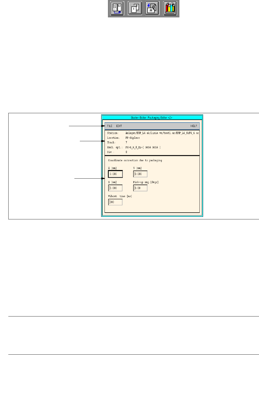
Fig. 13.1.10 Packaging Editor for Feeders
The Packaging Editor for feeders is subdivided into the following areas:
- Menu bar
- Identification field
- Editing area
Menu Bar
The menu bar contains the menus "FILE", "EDIT" and "HELP".
NOTE
The functions and the operation of the menus "FILE" and "HELP" are similar to those in other application
programs of the line computer and are described in detail in chapt. 2 "General Information on Using the
Program".
menu bar
identification field
editing area

User Manual Line Computer UNIX 13 Production Tools / Set-Up
Software Version 502.xx 10/2000 Issue 13.1 Set-Up Editor (Feeder Part and WPC/MTC Editors)
401
I
t I I
EDIT Menu
The EDIT menu contains the following options:
- Reset data
The corrections are deleted from all editing fields. The factory-set default values are redisplayed.
- Delete comp.
The component is deleted from the feeder division. This is indicated by a minus sign in the identifica-
tion field.
Identification Field
The identification field contains the following data which cannot be edited:
- Station: Name of the current station including "Anlagen/line/subline/set-up/station name"
- Location: Designation of the current feeder part
- Track: Number of the first track on which the selected feeder is set up
- Mach. opt.: Designation of the feeder and information on the components set up on it in both
divisions. A minus signifies that the division is not occupied.
- Div.: Number of the current feeder division
Editing Area
Corrections are entered in the editing area which are required for the accurate removal of the components.
When the Packaging Editor is opened, the factory-set default values or the values that were entered most
recently for a given component, are displayed in the editing fields.
The values in the editing area can be changed by clicking on the individual editing fields. The values are accepted
by pressing the Enter key after each correction made.
If the entries are not to be accepted, it is possible to reset the values on the EDIT menu to the default values
using the "Reset data" option.
13 Production Tools / Set-Up User Manual Line Computer UNIX
13.1 Set-Up Editor (Feeder Part and WPC/MTC Editors) Software Version 502.xx 10/2000 Issue
402
I
t I I
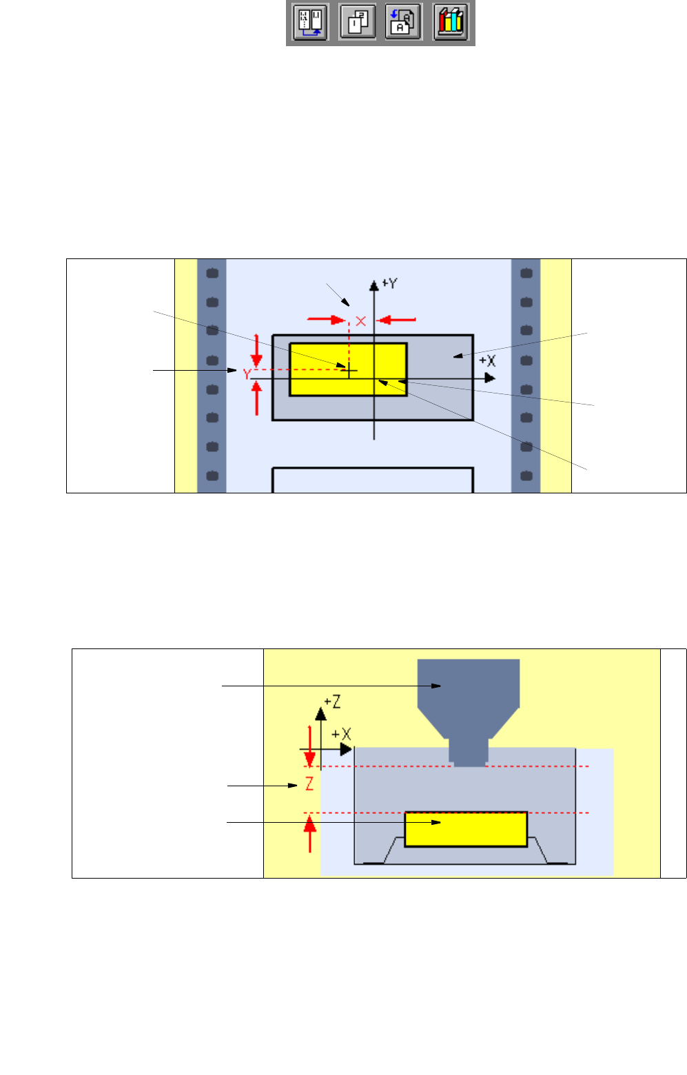
- X [mm]
Correction of the pick-up position in X-direction: offset from the component center to the feeder divi-
sion center (default value: 0.000, corresponds to the feeder division center). See Fig. 13.1.11.
- Y [mm]
Correction of the pick-up position in Y-direction: offset from the component center to the feeder divi-
sion center in Y-direction (default value: 0.000, corresponds to the feeder division center).
See Fig. 13.1.11.
Fig. 13.1.11 Correction of the Pick-Up Position in X-Direction and Y-Direction
- Z [mm]
Correction of the pick-up position in Z-direction: modified pick-up height of the component from the
feeder division (default value: 0.000, corresponds to the center of the feeder division).
See Fig. 13.1.12.
Fig. 13.1.12 Correction of the Pick-Up Position in Z-Direction
X [mm]
Y [mm]
component
center
tape pocket
component
feeder
division cente
r
nozzle
component
z [mm]