SIPLACE Line Computer UNIX.pdf - 第227页
User Manual Line Computer UNIX 6 Product / Package Form Software Vers ion 502.xx 10/2000 Issue 6.1 Pack age Form Editor 225 I t I I Creating a Grid Group ● Cli ck on Cre ate in the co mmand area of the ma in wind ow (see…
6 Product / Package Form User Manual Line Computer UNIX
6.1 Package Form Editor Software Version 502.xx 10/2000 Issue
224
I
t I I
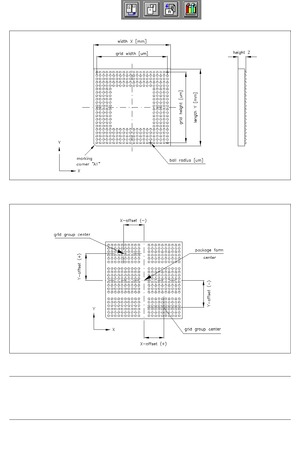
Fig. 6.1.23 Example "Ball Grid Array comprising a single grid group"
Fig. 6.1.24 Example "Ball Grid Array comprising 6 grid groups"
NOTE
For component centering by means of the Vision System, the component is placed onto the optical centering
station so that the marking of corner "A1" (see Fig. 6.1.23) is visible in the lower left corner of the Vision
System monitor. Corner "A1" can be identified by a bevel, notch, mark or the like.
User Manual Line Computer UNIX 6 Product / Package Form
Software Version 502.xx 10/2000 Issue 6.1 Package Form Editor
225
I
t I I
Creating a Grid Group
● Click on Create in the command area of the main window (see Fig. 6.1.1).
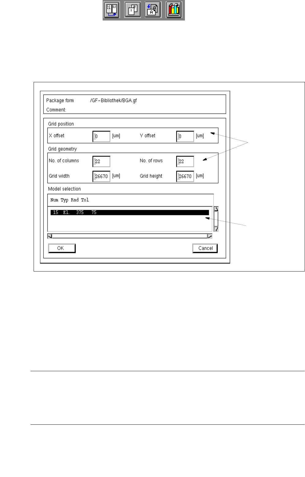
The window for editing the grid group data is opened (see
Fig. 6.1.25), and a ball is displayed in
the view area of the main window. .
Fig. 6.1.25 Window "Grid Group Description" (with values for the grid geometry already entered)
Procedure for Editing the Grid Group Data:
● Click on the individual editing fields and enter the values.
● After the data have been entered, click on OK to confirm your entries.
If the entered values are correct, the window is closed and the window for the model description is
opened containing a display of the defined grid group (see
Fig. 6.1.3).
NOTE
If invalid values were entered, a dialog box containing a corresponding error message is displayed
(see page 6 - 193). The fields containing the invalid values are surrounded by a red frame. The dialog
box must be acknowledged by clicking on OK first. Thereafter, the entries can be corrected and con-
firmed by clicking on "OK".
editing fields
selection field
"Models"

6 Product / Package Form User Manual Line Computer UNIX
6.1 Package Form Editor Software Version 502.xx 10/2000 Issue
226
I
t I I
Changing a Grid Group
● Click on the grid group in the view area of the main window.
The selected grid group is surrounded by a frame.
● Select the grid group once more by double-clicking.
The window for editing the grid group is opened (see
Fig. 6.1.25).
● Click on the editing field containing the value to be changed (position cursor in front of the value).
● Delete the value using the DELETE key and enter new value.
NOTE
If the RETURN key is pressed after a value has been changed, the graphical display of the
package form is automatically updated in the view area.
● After all desired changes have been made, click on OK.
If the entered values are correct, the window is closed.
The grid group is displayed in the view area with the modified dimensions.
Removing Balls From a Grid Group
To identify any possible absence of given "balls" within a grid, the balls concerned can be clicked on
in the "Grid group description" window.
Procedure:
● Click on each of the balls you want to remove using the right mouse button. The selected balls
are thereafter displayed in reverse video. By clicking once more with the right
mouse button their
state can be reversed again.
Allocating a New Ball Model to the Current Grid Group
If several ball models were already defined, the model data are displayed in the "Models" selection field
(see Fig. 6.1.25) and can thus be allocated to the current grid group.
The entry for a ball model comprises the following data:
Num = Number of the ball model
Typ = Type of the ball model (El. connection or Centering fiducial)
Rad = Radius of the ball model
Tol = Radius tolerance of the ball model