SIPLACE Line Computer UNIX.pdf - 第580页
18 Appendix User Manual Line Computer UNIX 18.1 General Spec ifications Concerning LC Dat a Software Version 5 02.xx 10 /2000 Issue 578 I t I I 18.1.2 Adhesive Patt ern 18.1.2.1 Adhesive Pattern Coordinates Pattern Coord…

User Manual Line Computer UNIX 18 Appendix
Software Version 502.xx 10/2000 Issue 18.1 General Specifications Concerning LC Data
577
I
t I I
18 Appendix
18.1 General Specifications Concerning LC Data
18.1.1 Data Constraints
For the definition of component/package form (GF), PCB and set-up data, certain limiting values imposed by
the line computer hardware used and the available data storage capacity must be taken into account.
At present, for the generation of the data listed below the following limits must be adhered to:
- Placement positions per gantry 1500 (80S) 2000 (80F)
- Single circuits (partial structures) per PCB 100
- Reference fiducial sets for PCB and
component position recognition 100
- Fiducials per reference fiducial set 3
- Ink spots per single circuit 1
- Number of components per set-up and station 240
- Package form (GF) descriptions per station 120
- Number of barcodes per component 240
18 Appendix User Manual Line Computer UNIX
18.1 General Specifications Concerning LC Data Software Version 502.xx 10/2000 Issue
578
I
t I I
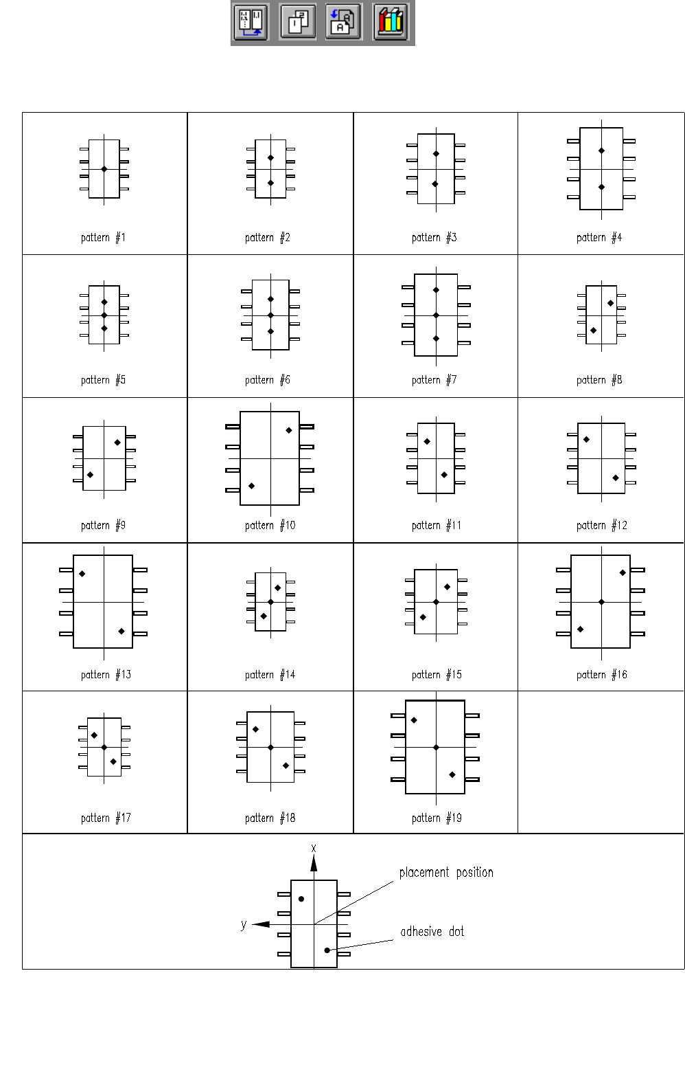
18.1.2 Adhesive Pattern
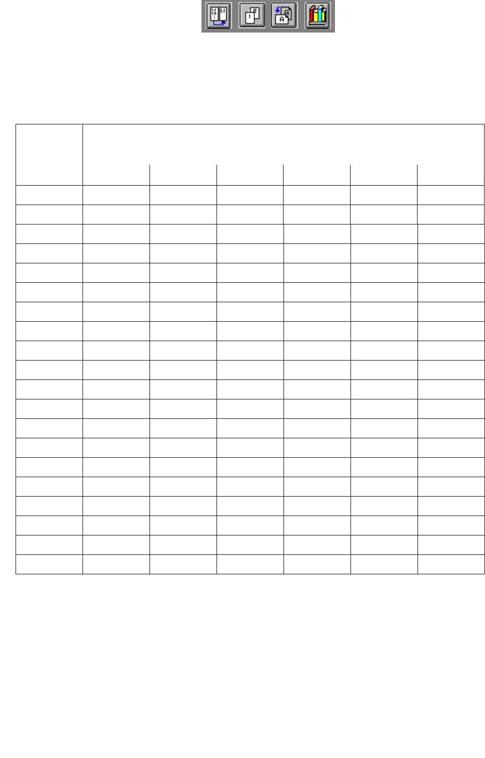
18.1.2.1 Adhesive Pattern Coordinates
Pattern Coordinates
Dot 1Dot 2Dot 3
# x 1y 1x 2y 2x 3y 3
100----
2 - - 2,20-2,20
3 - - 4,0 0- 4,00
4 - - 7,0 0- 7,00
5 0 0 2,2 0 - 2,2 0
6 0 0 4,0 0 - 4,0 0
7 0 0 7,0 0 - 7,0 0
8 - - 2,2 - 2,2 - 2,2 2,2
9 - - 4,0 - 4,0 - 4,0 4,0
10 - - 7,0 - 7,0 - 7,0 7,0
11 - - 2,2 2,2 - 2,2 -2,2
12 - - 4,0 4,0 - 4,0 - 4,0
13 - - 7,0 7,0 - 7,0 -7,0
14 0 0 2,2 - 2,2 - 2,2 2,2
15 0 0 4,0 - 4,0 - 4,0 4,0
16 0 0 7,0 - 7,0 - 7,0 7,0
17 0 0 2,2 2,2 - 2,2 - 2,2
18 0 0 4,0 4,0 - 4,0 - 4,0
19 0 0 7,0 7,0 - 7,0 - 7,0
20