SIPLACE Line Computer UNIX.pdf - 第578页
17 Practical Tips on Using the LC UNIX User Manual Line Computer UNIX 17.5 Line Control Software Version 5 02.xx 10 /2000 Issue 576 I t I I
User Manual Line Computer UNIX 17 Practical Tips on Using the LC UNIX
Software Version 502.xx 10/2000 Issue 17.5 Line Control
575
I
t I I
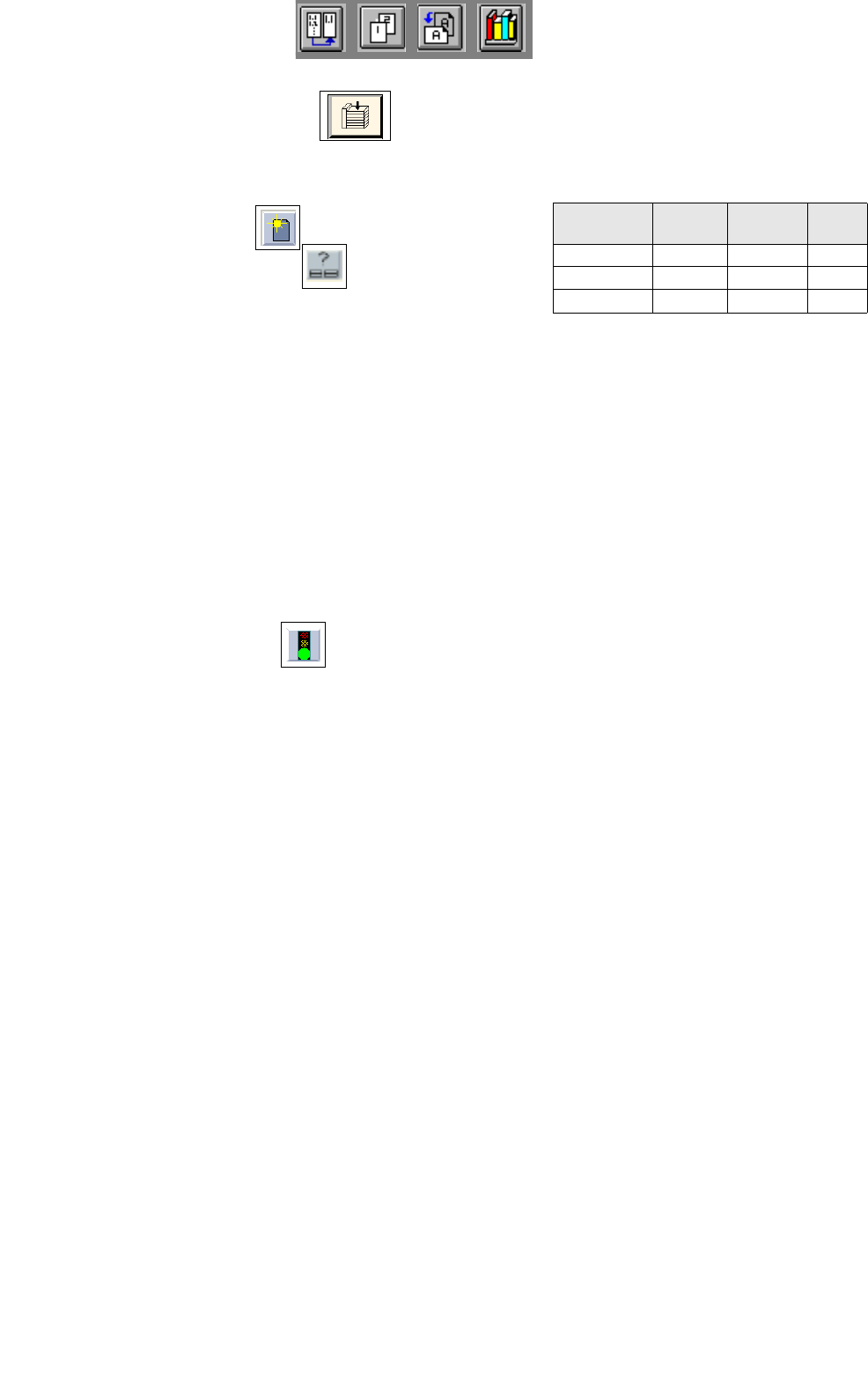
To open Job Control, proceed as follows:
1. On the desktop, click on the Job icon.
Job Control is opened.
To insert jobs in the job list, proceed as follows:
2. Activate the Create icon .
3. Activate the Edit support icon .
The Edit support Job Data is opened.
4. Successively select the following data by double-clicking: the PCB, here: Example_1.la, the line, here:
SMT.ak, the subline, here: Linie.va and the set-up, here: Examples01.ar.
The Edit support Job Data is closed, return to Job Control.
The selected data now appear in the editing area below the job list.
5. In the editing area click on the Lot name field and enter the lot name, here: ex1.
6. In the editing area click on the Lot size field and enter the lot size of the job, here: 10.
7. In the editing area click on the Lot type field and enter the lot type, here: F.
8. Click on the OK button.
The job is transferred to the job list. In the case of faulty entries, the field concerned is surrounded by a
red frame and an error message is displayed above the job list. Correct the entry.
9. Insert the remaining PCBs analogously, here: Example_2.la and Example_3.la, see chart.
To schedule a job, proceed as follows:
10. Click on the Schedule icon .
On the job list successively click on the individual jobs.
The jobs are checked for producibility and then passed to the station controller after the successful com-
pletion of the producibility check.
The Set-up Modification Generator is opened.
If errors are encountered during the producibility check, the status of the lot file is indicated by means of
an
E (Error). In the case of an error, proceed as follows:
— Click on the faulty job.
The job is highlighted.
— Click on the Error messages... option on the SERVICES menu.
The File display containing the error messages is displayed.
— Correct the errors displayed.
— Schedule the job once again.
To display and print out set-up changeover instructions:
11. In the Set-Up Modification Generator activate the Set-up modification instructions button.
The set-up changeover instructions are displayed.
12. On the FILE menu click on the Print command, then Print Line.
The set-up is printed out for all stations.
To change the set-up of stations and to confirm the changeover, proceed as follows:
13. Change the set-up of the stations in accordance with the set-up changeover instructions.
14. Once the set-up of the stations has been changed over, select the individual stations in the selection field
and click on the Set-up modified button for each station.
The job is only scheduled and placement is started, when the set-up changeover of all stations has been
completed.
The Set-Up Modification Generator is closed.
The assembly of the PCBs is started.
PCB Lot name Lot size
Lot
type
Example_1.la ex1 10 F
Example_2.la ex2 13 F
Example_2.la ex3 16 F

17 Practical Tips on Using the LC UNIX User Manual Line Computer UNIX
17.5 Line Control Software Version 502.xx 10/2000 Issue
576
I
t I I

User Manual Line Computer UNIX 18 Appendix
Software Version 502.xx 10/2000 Issue 18.1 General Specifications Concerning LC Data
577
I
t I I
18 Appendix
18.1 General Specifications Concerning LC Data
18.1.1 Data Constraints
For the definition of component/package form (GF), PCB and set-up data, certain limiting values imposed by
the line computer hardware used and the available data storage capacity must be taken into account.
At present, for the generation of the data listed below the following limits must be adhered to:
- Placement positions per gantry 1500 (80S) 2000 (80F)
- Single circuits (partial structures) per PCB 100
- Reference fiducial sets for PCB and
component position recognition 100
- Fiducials per reference fiducial set 3
- Ink spots per single circuit 1
- Number of components per set-up and station 240
- Package form (GF) descriptions per station 120
- Number of barcodes per component 240