SIPLACE Line Computer UNIX.pdf - 第536页
17 Practical Tips on Using the LC UNIX User Manual Line Computer UNIX 17.3 Description of Com ponents and PC Bs Software Version 5 02.xx 10 /2000 Issue 534 I t I I FIL E Save Opening P ackage Form Edito r Defining p acka…
User Manual Line Computer UNIX 17 Practical Tips on Using the LC UNIX
Software Version 502.xx 10/2000 Issue 17.3 Description of Components and PCBs
533
I
t I I
s
b
l
Bonding
Nozzles
Sensor
type
Placing
force
Processing Placem. head Centering Feeder
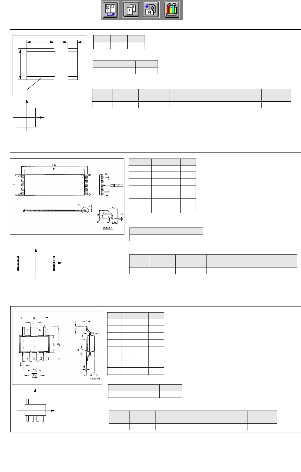
615, 618 9 2 Placing Turret head in head 12 mm tape
Pack. form type GF-No.
PDC 1503.gf
l mm b mm s mm
5,7 5,0 1,7
Y
X
Component
coordinate system
X
Y
Component
coordinate system
Pack. form type GF-No.
irregular FDC 1503.gf
Dim min. typ. max.
A--1.8
b 0.55 0.60 0.70
b
1
1.82 1.87 1.97
D6.36.56.7
E3.33.53.7
e
1
-3.81-
e
2
-1.27-
H
E
6.7 7.0 7.3
The pin group offset BG
Off
and the pin length B
L
are not indi-
cated and must be calculated from the following formulae (see
Fig. in On-line Help:
Nozzles
Sensor
type
Processing Placem. head Centering Feeder
615, 618 9 Placing Turret head in head 12 mm tape
BL
Width HE Width E
–
2
---------------------------------------------------------=
BGOff
Width HE PinLength BL
–
2
-------------------------------------------------------------------------=
Y
X
Component
coordinate system
Comp5.be: Plastic 32pin 8x20mm TSOP
Symbol Min Nom Max
A--1.2
b0.150.20.3
D 18.3 18.4 18.5
E 7.9 8.0 8.1
e-0.5-
H
D
19.8 20.0 20.2
L
1
-0.8-
Package form type GF-No.
regular FDC 1502.gf
The pin group offset BG
Off
is not indicated and
must be calculated using the following formula
(see Fig. in On-line Help):
BGOff
Width HE PinLength BL
–
2
-------------------------------------------------------------------------=
Nozzle
Sensor
type
Processing
Placem.
head
Centering Feeder
416 7 Placing IC-head external 32 mm tape
Comp6.be: Micro-X / MW
Comp4.be: Multi-Layer Capacitor, Type 2220
17 Practical Tips on Using the LC UNIX User Manual Line Computer UNIX
17.3 Description of Components and PCBs Software Version 502.xx 10/2000 Issue
534
I
t I I
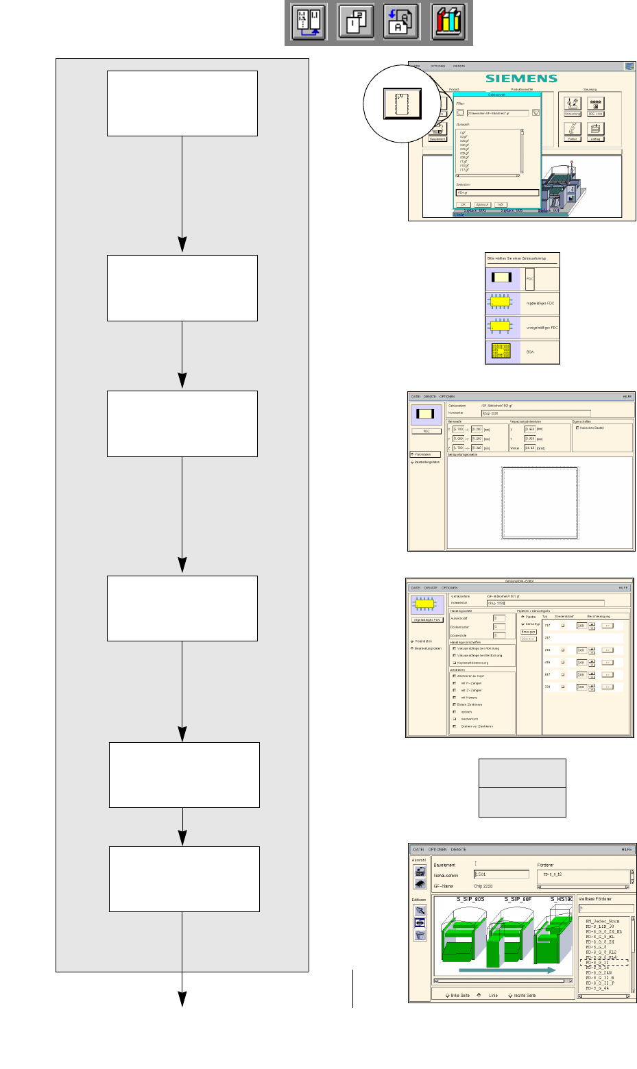
FILE
Save
Opening Package
Form Editor
Defining package
form type
Entering dimensions
Allocating package
form to a feeder
Entering handling
data
Package form description for package form 1501
continued on page 17-24
Saving
package form data
User Manual Line Computer UNIX 17 Practical Tips on Using the LC UNIX
Software Version 502.xx 10/2000 Issue 17.3 Description of Components and PCBs
535
I
t I I
17.2.2.1 Package Form Description
A) Description of a PDC using package form 1501 as an example
To open the Package Form Editor for package form 1501, proceed as follows:
1. On the desktop click on the icon of the Package Form Editor .
The file selection window is opened.
2. Click on the Selection editing field.
3. Enter the package form number, here: 1501.gf and click on the OK button.
The Package Form Editor with the package form type selection window is opened.
To define the package form type „PDC“ for package form 1501, proceed as follows:
4. In the package form type selection window click on the type PDC.
The selection window is closed.
5. In the Package Form Editor click on the Comment editing field, enter a unique comment, here: Chip
2220.
To enter the dimensions for package form 1501, proceed as follows:
6. In the Nominal Dimensions editing area enter the dimensions of the package form (click on the editing
field, enter value, confirm by pressing the Enter key), here: see chart:
The tolerances are entered automatically.
The package form is displayed with the tolerance range.
7. For this example the default values of the editing areas Packaging tolerances and Features are adopted,
no entries are required.
To enter the handling data for package form 1501, proceed as follows:
8. Activate the Handling data button.
The screen for entering the handling data is displayed.
9. Activate the Nozzle button in the command area.
10. Click on the Create button.
The Nozzle type selection window containing a list of the nozzle types is loaded.
11. Click on a nozzle, here: 615.
The selection window closes, the nozzle is transferred to the view area.
12. Select all other nozzles required accordingly, here: 618.
13. Activate the Sensor type button.
14. Click on the Create button.
The Sensor type selection window containing a list of the sensor types is opened.
15. Click on a sensor type, here: 9.
The selection window closes, the sensor type is transferred to the view area.
16. In the ’Handling values’ editing area, enter the applicable value in the Placement force field, here: 2.
17. In the ’Centering’ selection box, activate the applicable buttons, here: Centering in head.
18. In this example, the preselected settings for the handling values, the handling instructions and the ’Acce-
leration’ special handling option can be accepted as they are. No changes are required.
19. Click on the Save option on the FILE menu.
The data are now saved.
To allocate a feeder to package form 1501, proceed as follows:
20. Click on the Starting Feeder Editor option on the SERVICES menu.
The Feeder Editor is opened.
21. Activate the Allocate icon .
X
(Length l)
Y
(Width b)
Z
(Height s)
5.7 5 1.7