SIPLACE Line Computer UNIX.pdf - 第188页
6 Product / Package Form User Manual Line Computer UNIX 6.1 Package Form Ed itor Software Version 5 02.xx 10 /2000 Issue 186 I t I I View ar ea (see se ction 6. 1.2.6 ) If the Vision data scr een has been s electe d, the…
User Manual Line Computer UNIX 6 Product / Package Form
Software Version 502.xx 10/2000 Issue 6.1 Package Form Editor
185
I
t I I
Title bar
The title bar displays the directory in which the selected package form (or the GF-file) is contained, and the
number of the package form.
In the editing field below the title bar it is possible to enter a comment, e.g. the package form assigned to the
GF-no. (No inverted commas or quotation marks will be accepted. Max. 255 characters may be entered.)
The comment can be modified at any time, i.e. even after the package form has been saved.
Menu bar
The menu bar contains the "FILE", "SERVICES", "OPTIONS" and "HELP" menus.
A complete description of the "SERVICES" menu is contained in
section 6.1.2.1.
NOTE
Since the functions and operation of the "FILE", "OPTIONS" and "HELP" menus are similar to those in other
application programs of the line computer, they are described comprehensively in chapt. 2.
Area for general settings
The layout of the main window is determined by clicking on the buttons Vision data or Handling data.
Moreover, with customer-specific package forms it is possible to subsequently change the package form type
(except for the "BGA" type) using the <Package form type> button (see
section 6.1.2.2).
Selection fields (see
section 6.1.2.3 and section )
With the setting Vision data the characteristics of the current component type can be selected (see
section 6.1.2.3).
In the Handling data screen, the processing method for the current component type can be defined (see
section
6.1.2.10
).
Command area
The commands that may have been activated in this area, in combination with the settings FDC or BGA and
Vision data, enable pin groups and grid groups to be generated or deleted (see
section 6.1.2.4). Moreover,
the window for the description of the model data or group data for a selected object (pin, group, ball, grid group)
can be opened. If setting Handling data has been selected, nozzles and sensor types can be generated or
deleted (see
section 6.1.2.7).
Editing areas (see
section 6.1.2.5 and section 6.1.2.11)
If the Vision data setting has been selected, the dimensions of a package form (including its tolerances) are
defined by entering values in the respective editing fields of the editing areas. Moreover, the "cubic/non-cubic"
feature can be defined for FDCs and BGAs.
If Handling data setting has been selected, the placing force, the number of the adhesive pattern (which has
been defined for the current package form) and the adhesive amount to be dispensed can be entered.
NOTE
If the currently selected package form is a standard package form (number range 1 ... 1499), all handling data
can be changed. In the case of the vision data, only the values for the packaging tolerances can be edited. All
other vision data are write-protected.

6 Product / Package Form User Manual Line Computer UNIX
6.1 Package Form Editor Software Version 502.xx 10/2000 Issue
186
I
t I I
View area (see section 6.1.2.6)
If the Vision data screen has been selected, the current package form is displayed graphically in the view area
of the main window. After each change of the package form data the graphical image is automatically updated.
To change model or group data the respective graphic must be selected (see
Fig. 6.1.1).
In the view area of the Handling data screen, all nozzles or sensor system types created are displayed
depending on which button has been activated in the command area (see
Fig. 6.1.4 and Fig. 6.1.5).
In addition, with the aid of the buttons (see
Fig. 6.1.9) contained in the view area, it is possible to define the
special handling option "Acceleration" for nozzles created (see
section 6.1.2.9). (see Fig. 6.1.4).
6.1.2.1 SERVICES Menu
The SERVICES menu contains only one option with the following function:
- Starting the Feeder Editor for the definition of the feeders which are to be used for feeding the
current component (package form).
● Select menu item SERVICES --> Starting Feeder Editor.
The Feeder Editor is opened (see
chapt. 9).
User Manual Line Computer UNIX 6 Product / Package Form
Software Version 502.xx 10/2000 Issue 6.1 Package Form Editor
187
I
t I I
6.1.2.2 Area for general settings
The appearance (layout) of the main window is set by activating the "Vision data" or "Handling data"
button. The <Name of package form type> button is used for a subsequent change of the package form type.
Setting possibilities for the display in the main window
- Vision data This button is automatically activated by default when the Package Form
Editor is opened.
With this setting it is possible to edit the package form data that are
required for optical centering using the Vision System.
NOTE If the current package form is a standard package form
(numbers ranging from 1 ... 1499), the word "write-protected" is displayed
below the "Vision data" button. This means that none of the vision data
can be changed.
- Handling data With this setting all specifications for the processing of the particular
component type are defined.
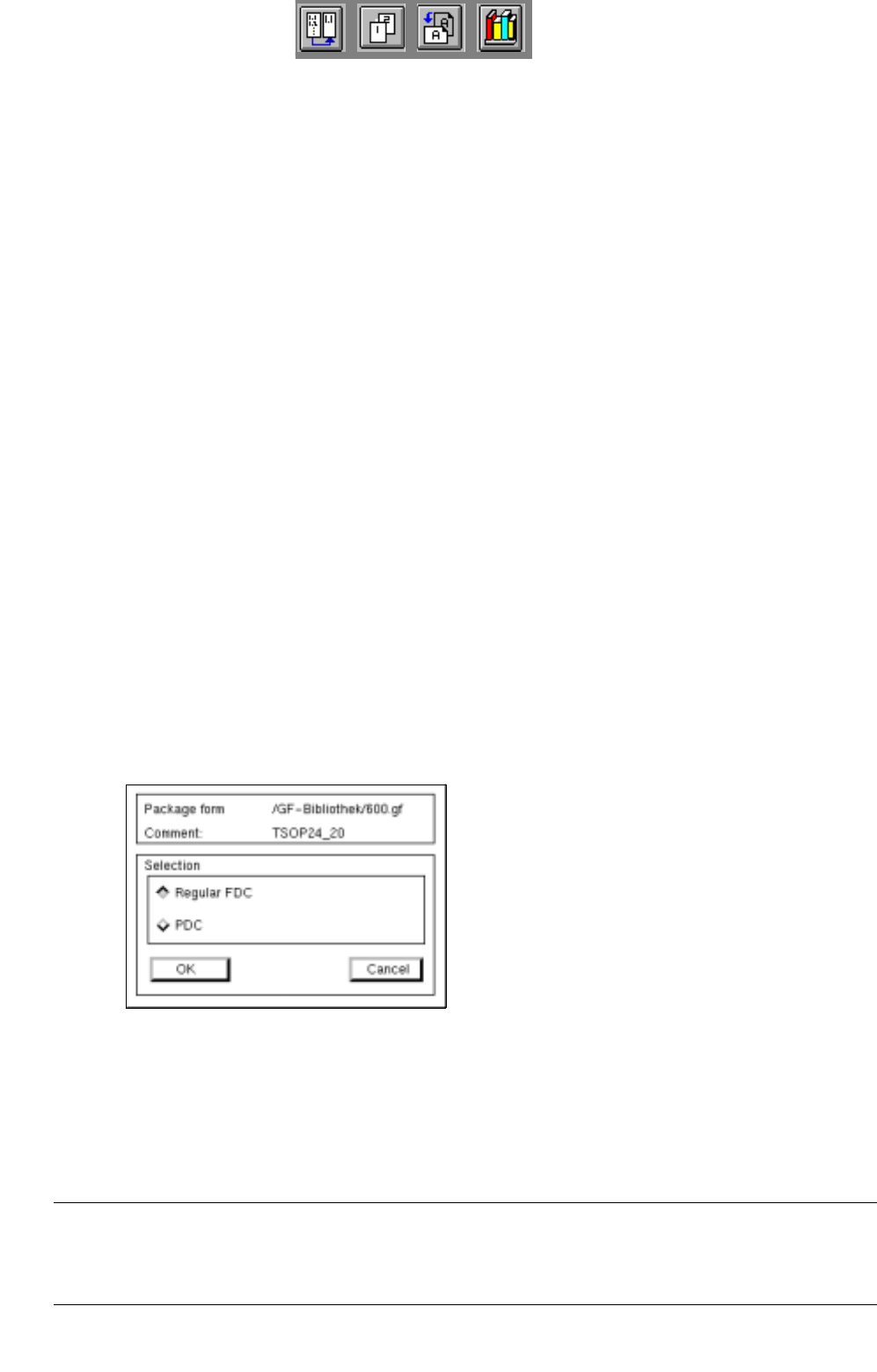
Changing the package form type
Once defined, FDCs and PDCs can still be changed into PDCs or FDCs, respectively. This is not possible
with BGA and standard package forms.
● Click on (e.g.) <irregular FDC>.
The dialog box for the selection of the new package form type is opened.
Depending upon whether the current package form is a PDC, a regular or irregular FDC, the following selection
possibilities for the new type are available:
- A PDC can be converted into a regular or irregular FDC.
- A regular FDC can be converted into an irregular FDC or a PDC.
- An irregular FDC can be converted into a regular FDC or a PDC.
NOTE
If the package form type is to be changed from an FDC to a PDC, a warning message is displayed
informing you that all model and group data will be deleted.