KE-2030使用说明书.pdf - 第164页
4 – 65 4.7.2.1 Exampl es of component dimensi ons See the f ollowing figur es to create dat a. • Square chip • MEL F (horizontal) (horizontal)
4 – 64
2) Tack control section to be displayed when “Stick” is selected as the component
package
3) When you select “Bulk” as the component package
When you change the “Component packaging” setting, the “Sply” (Supply) menu
item of Pick data is set to “Auto”.
④ Outer dimensions (Width, Length)
Enter the component width and length, using the formula bar.
Input range: 0.01 mm to 150.00 mm
⑤ Outer dimensions (Height)
Enter the component height using the formula bar.
Input range: 0 to 25.00 mm
⑥ Other
Pick depth
Enter the distance from the side picked up with a nozzle to the top of the
projection of a component with using the formula bar.
Input range: 0 to 25.00 mm
The default value is “0”. Entry to this item may be required for a
component whose surface is not flat such as a connector.
Normally the default value can be applied to this item.
4 – 65
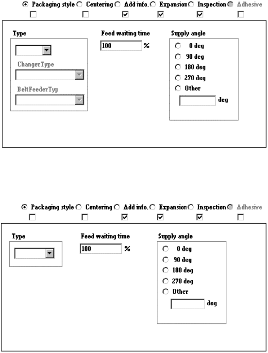
4.7.2.1 Examples of component dimensions
See the following figures to create data.
• Square chip
• MELF
(horizontal)
(horizontal)
4 – 66
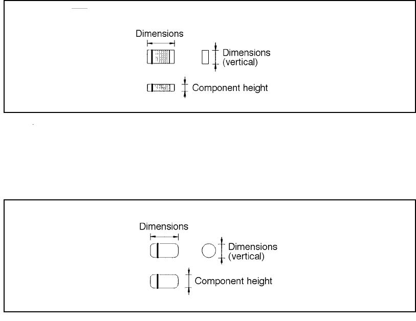
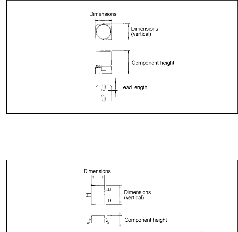
• Aluminum electrolytic capacitor
• SOT
(horizontal)
(horizontal)