KE-2030使用说明书.pdf - 第221页
4 – 122 Data ty pe Item Error conditions Optimization option Non-stop option − The IC recov ery belt is used on the rear side although “Front to Rear” is selected from the “Primary Secondary” pull-down menu - If the area…
4 – 121
Data type Item Error conditions
Placement of vision
components (0.8 <= the
smallest pitch < 1.0 mm) (Ball
components)
The optional 37.5 mm, 27 mm or 18 mm VCS is not set
in Placement data of vision components whose
minimum pitch is 0.8 mm or wider, but narrower than 1.0
mm.
*1
Placement of vision
components (0.5 <= the
smallest pitch < 0.8 mm) (Ball
components)
The optional 27 mm or 18 mm VCS is not set in
Placement data of vision components whose minimum
pitch is 0.5 mm or wider, but narrower than 0.8 mm.
*1
Placement of vision
components (0.35 <= the
smallest pitch < 0.5 mm) (Ball
components)
The optional 18 mm VCS is not set in Placement data of
vision components whose minimum pitch is 0.35 mm or
wider, but narrower than 0.5 mm.
*1
Pick-up of all balls or all lands
vision recognition components
The BGA vision recognition function cannot be used
with the station in Pick data of all balls or all lands vision
recognition components.
*1
Number of all balls or all lands
vision recognition ball pattern
components
The number of user-defined ball pattern components in
Pick data is found to exceed 10 with the all balls or all
lands vision recognition function.
*1
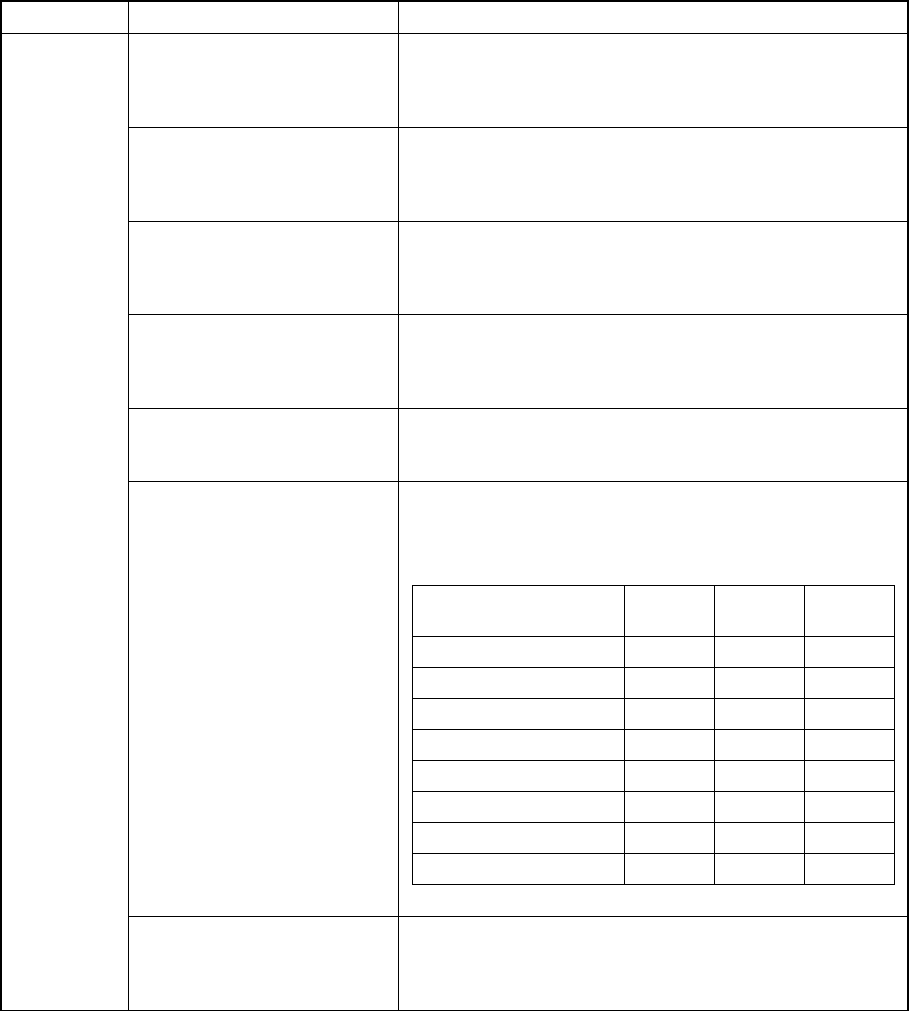
Error conditions of the VCS recognition type specified
on the MSL setup menu and the light type specified in
Light data
*1
VCS recognition type
Reflective
light
Penetra-
tive light
Side light
No recognition
×
×
×
BGA vision recognition
×
×
○
Penetrative recognition
×
○
×
Reflective recognition
○
×
×
BGA, penetrative
×
○
○
BGA, reflective
○
×
○
Penetrative, reflective
○
○
×
BGA, Penetrative, reflective
○
○
○
Light type
Vision data
Component for which you can
select “Vision centering
component” as its component
type
The component size is smaller than 0.6 mm. *1

4 – 122
Data type Item Error conditions
Optimization
option
Non-stop option
− The IC recovery belt is used on the rear side although
“Front to Rear” is selected from the “Primary Secondary”
pull-down menu
- If the area is set to “front” or “rear”.
− A DTS is installed on your system, and “No” is not selected
from the “Feeder” pull-down menu on the “Non-Stop”
option tab.
− A tray holder is used and the menu item “Feeder” on the
“Non-stop” tab is not set to “No”.
- “Arrange priority” is set to a KE-2000 on the “Non-Stop”
tab.
(That is, the line includes a KE-2000 station, and the
“Arrange priority” is set to “Line” on the “Non-Stop” option
tab.
− A belt feeder is used and the menu item “Feeder” on the
“Non-stop” tab is not set to “No”.
− “No” is not selected from the “Feeder” pull-down menu on
the “Non-Stop” option tab even though the machine is not
designed for not-stop operation (this option is not installed
on the station).
*1: Items applicable to machines other than a KE-2030
4 – 123
To check a general-purpose vision component, the system assigns priorities to its data as
shown below, then performs the data coherence check in the order of the priorities.
If an error is detected when the system checks data whose priority is relatively higher, the
system finishes checking data on the component at that point.
The detailed error message appears below the item at which an error is detected.
1. Component data
1.1 Component type (lead components, ball components, outline-recognition
components and other components whose vision is used for centering)
1.2 Dimensions
2 Element data
2.1 Element group
2.2 Element
3 Control data
3.1 Light type
3.2 Number of divisions
3.3 Applied VCS
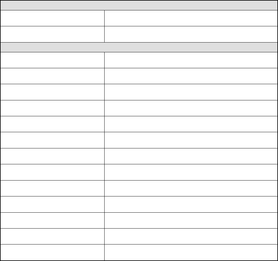
Check that displays the error message “Wrong element group setting” on the screen
Component dimension X
The offset coordinate X is the absolute value of the component
dimension or larger value.
Component dimension Y
The offset coordinate Y is the absolute value of the component
dimension or larger value.
Check that displays the error message “Wrong element setting” on the screen
Component dimension X
The offset coordinate X is the absolute value of the component
dimension or larger value.
Component dimension Y
The offset coordinate Y is the absolute value of the component
dimension or larger value.
Lead component whose dimension X is
from 2.5 mm to 74.0 mm
Component whose pitch X is not within the range between 0.5 mm
and 22 mm
Lead component whose dimension X is
from 2.3 mm to 68.0 mm
Component whose pitch X is not within the range between 0.4 mm
and 15.0 mm
Lead component whose dimension X is
from 2.1 mm to 48.0 mm
Component whose pitch X is not within the range between 0.3mm
and 11.0 mm
Lead component whose dimension X is
from 1.9 mm to 31.0 mm
Component whose pitch X is not within the range between 0.2 mm
and 6.5 mm
Ball component whose dimension X is
from 2.0 mm to 74.0 mm
Component whose pitch X is not within the range between 1.0 mm
and 22.0 mm
Ball component whose dimension X is
from 1.2 mm to 68.0 mm
Component whose pitch X is not within the range between 0.8 mm
and 15.0 mm
Ball component whose dimension X is
from 1.0 mm to 48.0 mm
Component whose pitch X is not within the range between 0.5 mm
and 11.0 mm
Ball component whose dimension X is
from 0.6 mm to 31.0 mm
Component whose pitch X is not within the range between 0.35 mm
and 6.5 mm
Ball component whose dimension Y is
from 2.0 mm to 150.0 mm
Component whose pitch Y is not within the range between 1.0 mm
and 22.0 mm
Ball component whose dimension Y is
from 1.2 mm to 100.5 mm
Component whose pitch Y is not within the range between 0.8 mm
and 15.0 mm
Ball component whose dimension Y is
from 1.0 mm to 72.0 mm
Component whose pitch Y is not within the range between 0.5 mm
and 11.0 mm