KE-2030使用说明书.pdf - 第348页
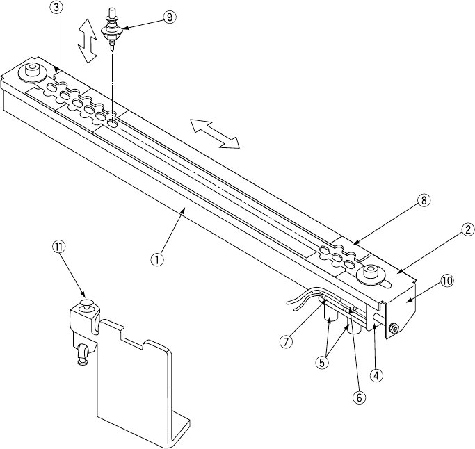
6 − 2 21 20 6 5 4 3 2 1 ① ATC brack et ⑦ ATC CLOSE sensor ② Slide plate ⑧ ATC number s (1 to 21) ③ Nozzle outer support ⑨ Nozzle ④ Air cylinder ⑩ ATC ang le bracket ⑤ Speed controllers ⑪ Valve ⑥ ATC OPEN sensor Figure 6.…
6 − 1
CHAPTER 6 PRODUCTION PROCEDURES
6.1 Preparations
6.1.1 Component feeders
Make sure that all component feeders (the tape feeders and the stick feeders,) are
mounted in place correctly.
6.1.2 ATC
Check to see if the number of each nozzle mounted on the ATC is equal to the ATC
number and nozzle number selected in the “ATC nozzle assignment” item of the
Machine Setup menu.
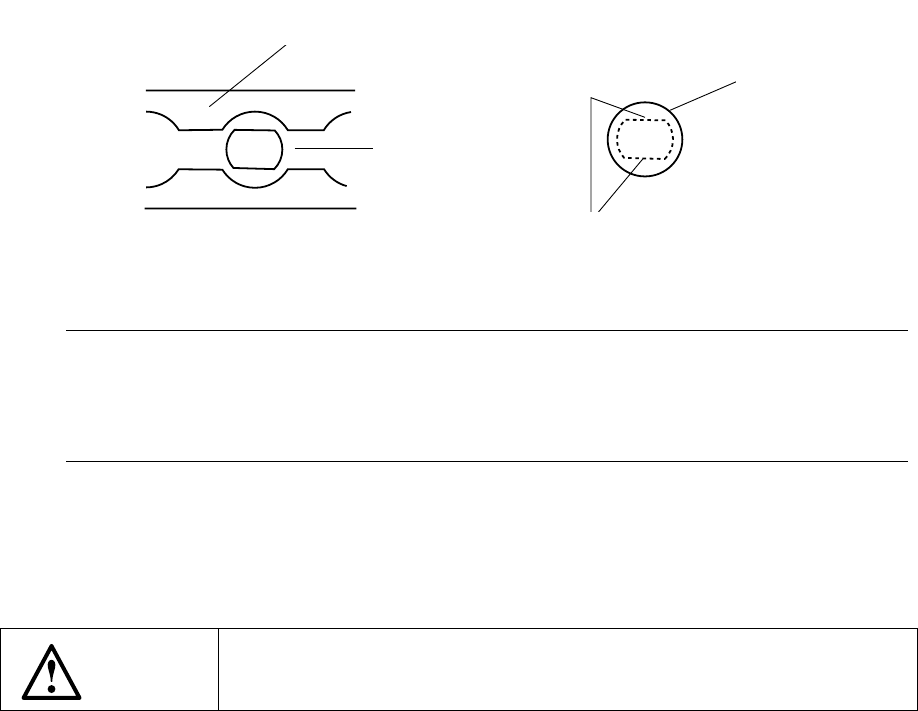
<Mounting and dismounting nozzles on the ATC>
Procedure
1. Turn off the power of the machine. Set the valve ⑪ to OFF.
2. Open the slide plate ②.
3. With aligning the flat portion of the nozzle ⑨ with the long hole of the ATC
bracket ①, mount the nozzle ⑨ onto the ATC.
Figure 6.1.2.1
Notes:
•
Mount the nozzle
⑨
so that it cannot be inclined on the ATC bracket
①
•
Return the nozzles where they were. When a nozzle is replaced,
perform the laser height adjustment for nozzle assignment of the setup
data
4. Nozzles are also dismounted in this state.
5. Do not attach the nozzle directly to the head. (The face of the laser becomes
dirty and this can cause errors.)
WARNING
Before starting to work, turn off the power of the machine to avoid a risk
of injury caused by unpredictable activation of the machine.
Slide plate ②
ATC bracket ①
When the slide plate 2 is opened
Nozzle ⑨
Flat portions
6 − 2
21
20
6
5
4
3
2
1
①
ATC bracket
⑦
ATC CLOSE sensor
②
Slide plate
⑧
ATC numbers (1 to 21)
③
Nozzle outer support
⑨
Nozzle
④
Air cylinder
⑩
ATC angle bracket
⑤
Speed controllers
⑪
Valve
⑥
ATC OPEN sensor
Figure 6.1.2.2
Close
Open
6 − 3
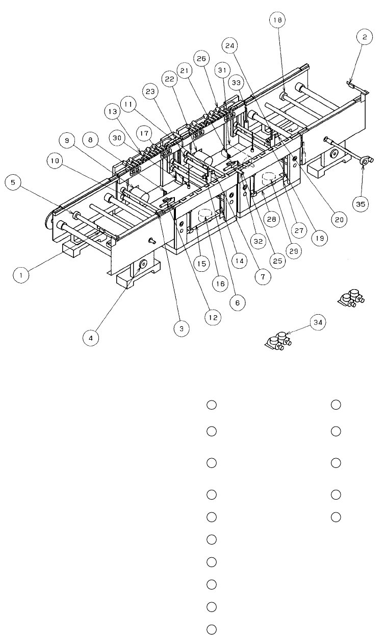
6.1.3 Board transfer section
6.1.3.1 PWB transfer mechanism
Figure 6.1.3.1
①
IN sensor
⑪
Stopper at the entrance
21
BU sensor at the exit
31
YC motor
②
OUT sensor
⑫
X pusher at the
entrance (Edge
reference option)
22
Center motor at the exit
32
C. board chuck sensor
③
Wait sensor
⑬
Y pusher at the
entrance (Edge
reference option)
23
Drive shaft (at the exit)
33
S. board chuck sensor
④
IN motor
⑭
Centering pin at the
entrance
24
Stopper at the exit
34
Depressure valve
(Edge reference option)
⑤
Drive shaft (IN)
⑮
BU table at the
entrance
25
X pusher at the exit
(Edge reference option)
35
Hand knob
⑥
Stop sensor at the
entrance
⑯
BU motor at the
entrance
26
Y pusher at the exit
(Edge reference option)
⑦
C.OUT sensor at the
entrance
⑰
BU pin
27
Centering pin at the
exit
⑧
BU sensor at the
entrance
⑱
Drive shaft (OUT)
28
BU table at the exit
⑨
Center motor at the
entrance
⑲
Stop sensor at the exit
29
BU motor at the exit
⑩
Drive shaft
(at the entrance)
⑳
C.OUT sensor at the
exit
30
YC origin sensor/+ limit
sensor/- limit sensor