KE-2030使用说明书.pdf - 第401页
6 − 55 In the same m anner, when the Operat ion option “Pick and trace bef ore r etry.” is checked, t he system picks up a com ponent and track s this pick ing-up oper ation according t o the specif ied requir ements bef…
6 − 54
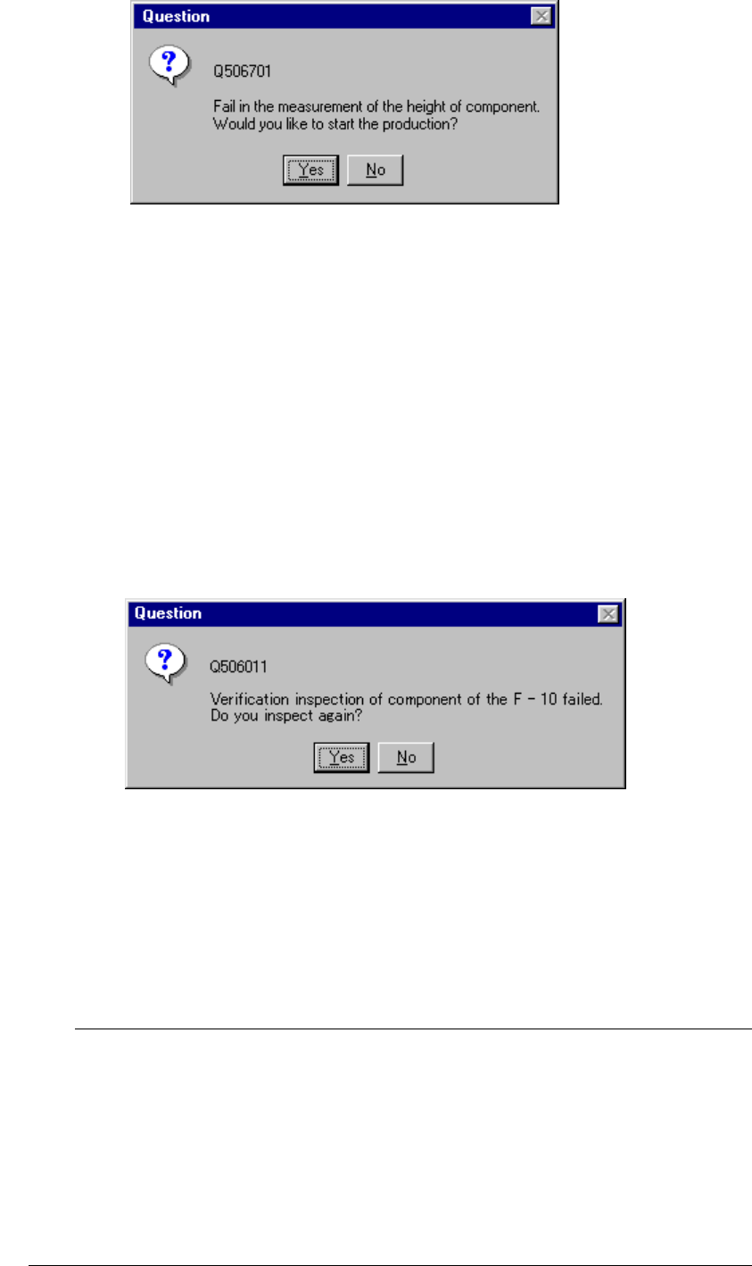
Figure 6.4.1.2 "Question" dialog box
• When you click the <Yes> button, the system remeasures a component fed by a
feeder which failed to be measured.
• When you click the <No> button, the system measures the height of a component
fed by the next feeder whose stocked components run out, or tries to restart
production.
■ In the same manner, when you check the check box “The verification inspection is
done on restart component run out.” on the Production (Pause) tab invoked from
the Operation option dialog box, the machine restarts production after performing
verification check for a chip or MELF component that runs out.
◇ If the machine fails to perform a verification check, the dialog box shown in
Figure 6.4.1.2.1 appears on the screen.
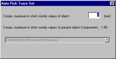
Figure 6.4.1.2.1 Question dialog box
• When you click the <Yes> button, the system re-checks components of a feeder
that failed to be checked.
• When you click the <No> button, the system performs a verification check for
components fed by the next feeder whose stocked components run out, or tries to
restart production.
If you check both of the check boxes “Re-measure component height
when components run out.” and “The verification inspection is done
on restart component run out.” on the Production (Pause) tab invoked
from the Operation option dialog box, the system measures the height of all
applicable components, and then performs a verification check.
It does not measure the component height and performs a verification
check alternately.
The system does not perform a verification check for a component whose
height fails to be measured.
L
6 − 55
In the same manner, when the Operation option “Pick and trace before retry.” is
checked, the system picks up a component and tracks this picking-up operation
according to the specified requirements before resuming the suspended production.
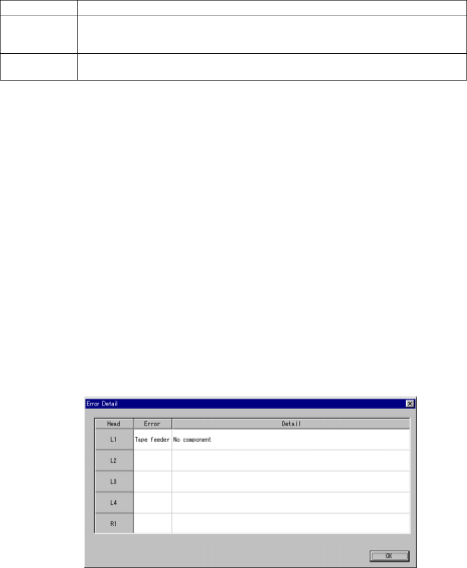
Before picking up and tracking a component, the “Auto Pick Trace Set” dialog box
appears on the screen as shown in Figure 6.4.1.3.
Figure 6.4.1.3 “Auto Pick Trace Set” dialog box
Enter the maximum length of the shorter side of a component to be picked up/tracked
in the input area. The system will not pick up and track a component whose shorter
side is longer than the value you specified here.
When you press the <START> switch, the system picks up and tracks a component,
and then resumes the suspended production. When you press the <STOP> switch,
the system enters Pause mode again.
The combo box displayed on the dialog box above indicates the setting of the
Operation option, and you cannot change or select it.
6 − 56
③ Production restart mode
How production restarts when the <START> switch on the operation panel is
pressed differs as shown below, depending on the selection of the radio
button on the dialog box.
Restart mode Operation when production is restarted
Retry Searches all alternative feeders for the runout components, and if all the feeders have run out
of the components, all the feeders are fully loaded with the components. Then, operation
restarts from the current pick and placement cycle.
Skip Skips the components which have been run out, and production starts from the next pick
cycle.
(3) Tracking and pick position correction of a feeder where components run out
① Feeders to be tracked
The system can track a tape feeder, stick feeder, and bulk feeder; all feeders
where a retry over error occurs or components run out. However, it does not
track a feeder which is set as "Unused".
② How to enter Tracking mode
Press one of the CAMERA, HEAD and HMS device keys of the HOD to
activate its function.
③ Other operation
The other operations during this tracking and correction are the same as
those for pick position tracking.
(4) Detailed information
When you click the <Detail> button, the system displays the list of the heads that
cause an error.
Figure 6.4.1.3 “Error Detail” dialog box (Screen example when you use a KE-2020)
* The actually displayed names under the caption “Head” on the screen shown
in Figure 6.4.1.3 vary depending on the model you use.