KE-2030使用说明书.pdf - 第518页
7 − 24 7.2.2.7 Device enabl e A screen appears as shown in Figure 7.2. 2.7.1 “ Device enable setting dialog box with tabs” when [Device enable] is selected from the [Sett ing Gr oup] menu. Figure 7.2.2. 7.1 Device enabl …
7 − 23
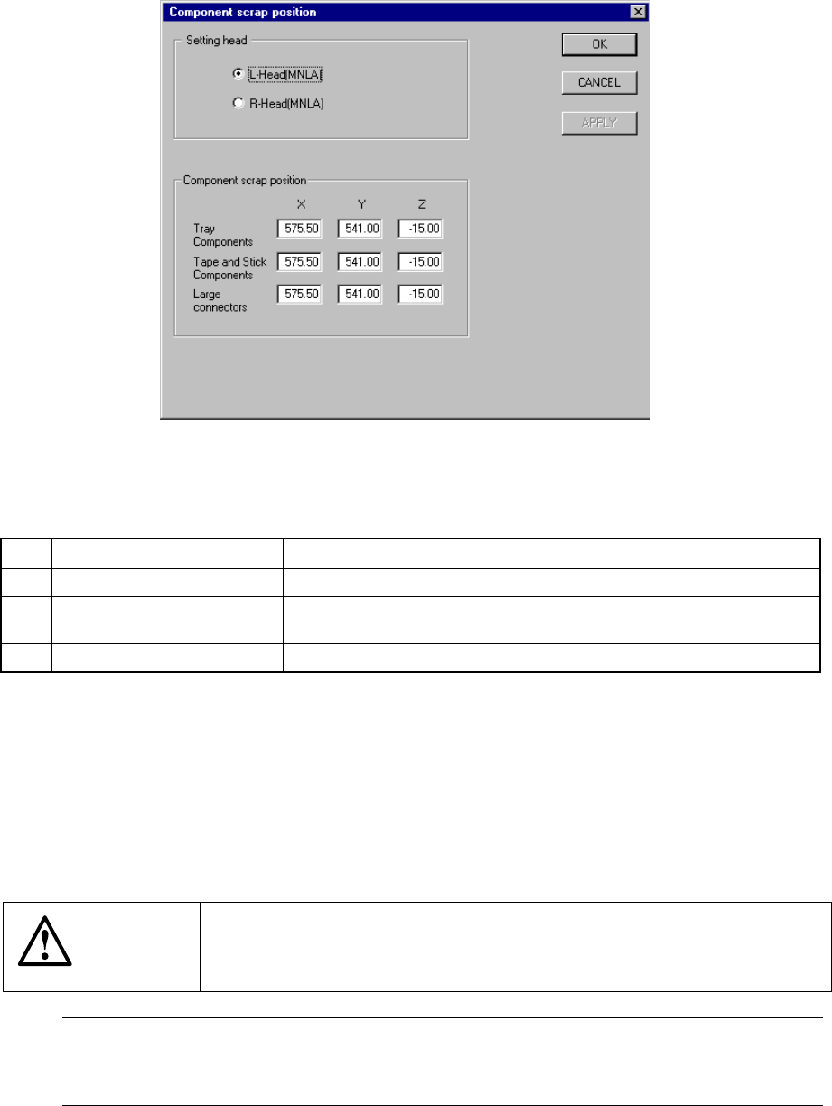
7.2.2.6 Component scrap position
A screen appears as shown in Figure 7.2.2.6.1 “Component scrap position setting
dialog box” when [Component scrap position] is selected from the [Setting Group]
menu.
Figure 7.2.2.6.1 Component scrap position setting dialog box
(1) Setting items
No. Item Description
1 Tray Components (X, Y, Z) The scrap position for IC components
2 Tape & Stick Components
(X, Y, Z)
The scrap position for chip components
3 Large Connectors (X, Y, Z) The scrap position for large components
(2) Setting the position
− Key in X, Y, and Z coordinate values directly from the keyboard.
− Use the HOD to teach and enter the coordinates. In this case, if either X or
Y is in focus bothe values are taught, then entered.
− Z must be in focus to teach the Z coordinate.
CAUTION
To avoid a risk of injury, do not place your hand in the machine, nor
move your face or head close to the machine during operation of the
HOD.
Note: The left head cannot be as the component scrap position on the right side.
The right head cannot be set to the component scrap position on the left side
either.
7 − 24
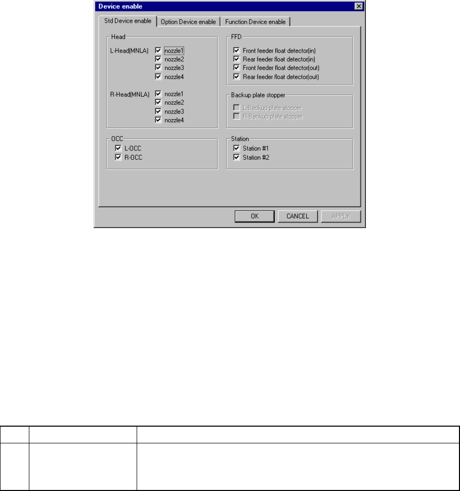
7.2.2.7 Device enable
A screen appears as shown in Figure 7.2.2.7.1 “Device enable setting dialog box
with tabs” when [Device enable] is selected from the [Setting Group] menu.
Figure 7.2.2.7.1 Device enable setting dialog box with tabs
When you click the corresponding tab, the “Std Device enable ”, “Option Device
enable ” or “Function Device enable ” dialog box appears.
7.2.2.7.1 Std Device enable
When you click the “Std Device enable” tab, a screen appears as shown in Figure
7.2.2.7.1 “Device enable 1 setting dialog box”. The “Device enable 1” dialog box
is displayed as the initial screen immediately after you select the [Std Device
enable] menu item from the [Setting Group] pull-down menu.
(1) Setting items
No. Item Description
1 Std Device enable Unit to be used/not used
If a system unit malfunctions that unit may be defined as “a unit not used”
using this menu item. This allows the pick-and-place sequence to be
executed without modifying the production program data.
Table 7.2.2.7.1 shows whether or not a pick-and-place sequence can be
completed if the production program requires the unit defined as to be used
before it can complete itself.
(2) Setting the unit
− Specify the device unit to be used with the check box.
− A device unit which is not installed as an option (displayed in dimmed
characters) cannot be checked.
z Zeroing is required again when changing the head status from as not to be
used to as to be used.
7 − 25
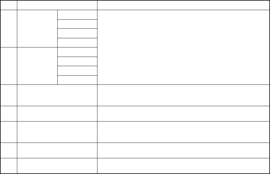
(3) Production operation
Table 7.2.2.7.1 Placement when a unit is set as “Unused”
No. Unit Production operation
nozzle 1
nozzle 2
nozzle 3
1 L-Head
nozzle 4
nozzle 1
nozzle 2
nozzle 3
2 R-Head
nozzle 4
Components to be placed by these heads are not placed.
The Optimization utility does not assign any component to these
heads.
3 L-OCC Placement of components is carried out without BOC mark or bank
mark recognition.
Placement of IC mark components is not carried out.
4 R-OCC Placement of components is carried out without bank mark
recognition.
5 Feeder float detector
(Front inside, front outside,
rear inside and rear outside)
This function is disabled but placement of components is carried out.
6 Support plate stopper
(Left, Right)
This function is disabled but placement of components is carried out.
7 Station
(IN, OUT)
This function is disabled but placement of components is carried out.
(for a KE-2030 only).