KE-2030使用说明书.pdf - 第349页
6 − 3 6.1.3 Board transfer sect ion 6.1.3.1 PWB transfer mechanism Figure 6.1.3. 1 ① IN sensor ⑪ Stopper at the entrance 21 BU sensor at the ex it 31 YC motor ② OUT sensor ⑫ X pusher at the entrance (Edge reference optio…
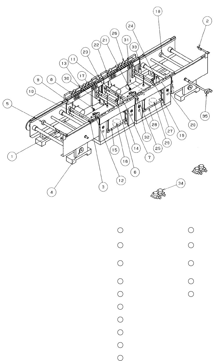
6 − 2
21
20
6
5
4
3
2
1
①
ATC bracket
⑦
ATC CLOSE sensor
②
Slide plate
⑧
ATC numbers (1 to 21)
③
Nozzle outer support
⑨
Nozzle
④
Air cylinder
⑩
ATC angle bracket
⑤
Speed controllers
⑪
Valve
⑥
ATC OPEN sensor
Figure 6.1.2.2
Close
Open
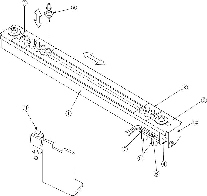
6 − 3
6.1.3 Board transfer section
6.1.3.1 PWB transfer mechanism
Figure 6.1.3.1
①
IN sensor
⑪
Stopper at the entrance
21
BU sensor at the exit
31
YC motor
②
OUT sensor
⑫
X pusher at the
entrance (Edge
reference option)
22
Center motor at the exit
32
C. board chuck sensor
③
Wait sensor
⑬
Y pusher at the
entrance (Edge
reference option)
23
Drive shaft (at the exit)
33
S. board chuck sensor
④
IN motor
⑭
Centering pin at the
entrance
24
Stopper at the exit
34
Depressure valve
(Edge reference option)
⑤
Drive shaft (IN)
⑮
BU table at the
entrance
25
X pusher at the exit
(Edge reference option)
35
Hand knob
⑥
Stop sensor at the
entrance
⑯
BU motor at the
entrance
26
Y pusher at the exit
(Edge reference option)
⑦
C.OUT sensor at the
entrance
⑰
BU pin
27
Centering pin at the
exit
⑧
BU sensor at the
entrance
⑱
Drive shaft (OUT)
28
BU table at the exit
⑨
Center motor at the
entrance
⑲
Stop sensor at the exit
29
BU motor at the exit
⑩
Drive shaft
(at the entrance)
⑳
C.OUT sensor at the
exit
30
YC origin sensor/+ limit
sensor/- limit sensor
6 − 4
6.1.3.2 Basic adjustment
(1) Adjustment of the distance between the transfer rails (Figure 6.1.3.1)
1) Mount the hand knob
35
to the handle shaft and turn the handle to set the
distance between the rails to the width of a PC board to be transferred +1
mm.
2) Move the PC board to be produced fully from one end of the rails to the other
end and make sure that the PC board can move smoothly on the rails.
3) When completing the adjustment, remove the handle knob and keep it on the
storage tray on the side of the machine.
WARNING
Before starting to work, turn off the power of the machine to avoid a risk
of injury caused by unpredictable activation of the machine.
(2) Adjustment of the centering pin (Omitted when the board outline is used for
reference) (Figure 6.1.3.2, Figure 6.1.3.3)
1) Turn off the power, and also turn off the air valve.
2) Loosen the M4 hexagon socket head bolts
37
used to fix the guide block
36
1 with the ball driver (supplied tool).
3) Move the stopper
⑪
24
by hand, and push the produced board (avoid the
center of the board and any cutouts of the board to contact the stopper)
against the stopper (as far as it goes).
4) Slide the guide block
36
in the X direction, and fit the centering pins
⑭
27
with the reference holes of the board. Allow a space of 0.5 mm between the
stopper
⑪
24
and the board. If the space is too small, the board may not be
set with ease.
5) While holding the guide block pushed to the guide rail
38
, tighten the M4
hexagon socket head bolts
37
to lock the guide block.
Notes:
①
Adjustment procedures 1) through 5) under (2) above can also be
adjusted manually by turning on the power and the air valve, and
using the independent control in the conveyor system of the manual
control and the automatic control.
②
When the centering pin is moved, be sure to reenter the position of
the reference pin for the machine setup. If it is not reentered, the
reference position of the data is made differently.
③
There is no need of adjustment for the board of same specifications.
④
Adjustment items 1) through 5) under item (2) above can be
performed by turning on the machine and using independent control
of transportation system, manual control or automatic control.
(See Chapter 9 " MANUAL CONTROL ".)
WARNING
Before starting to work, turn off the power of the machine to avoid a risk
of injury caused by unpredictable activation of the machine.