KE-2030使用说明书.pdf - 第684页
12 − 13 3. How to Use a Gripper Nozzle 3.1 Load information on a gri pper nozzle from a fl oppy disk on the Machine Setup menu . * Once you load inform ation, it is st ored on the m achine, so you do not have to perf orm…
12 − 12
(5) Applicable components and packaging style
Applicable components: • Connectors (the top side cannot be picked up
with a standard nozzle)
• Lead pitch (1 mm or wider)
• Weight: 5 kg or less (This value is subject to
change depending on the shape of a
component.)
• There should be a flat area on the top of a
component against which the fixed arm can be
pushed. (to prevent a component from inclining
when the X-Y axes moves)
Packaging style: • Taping and tray
◇
◇◇
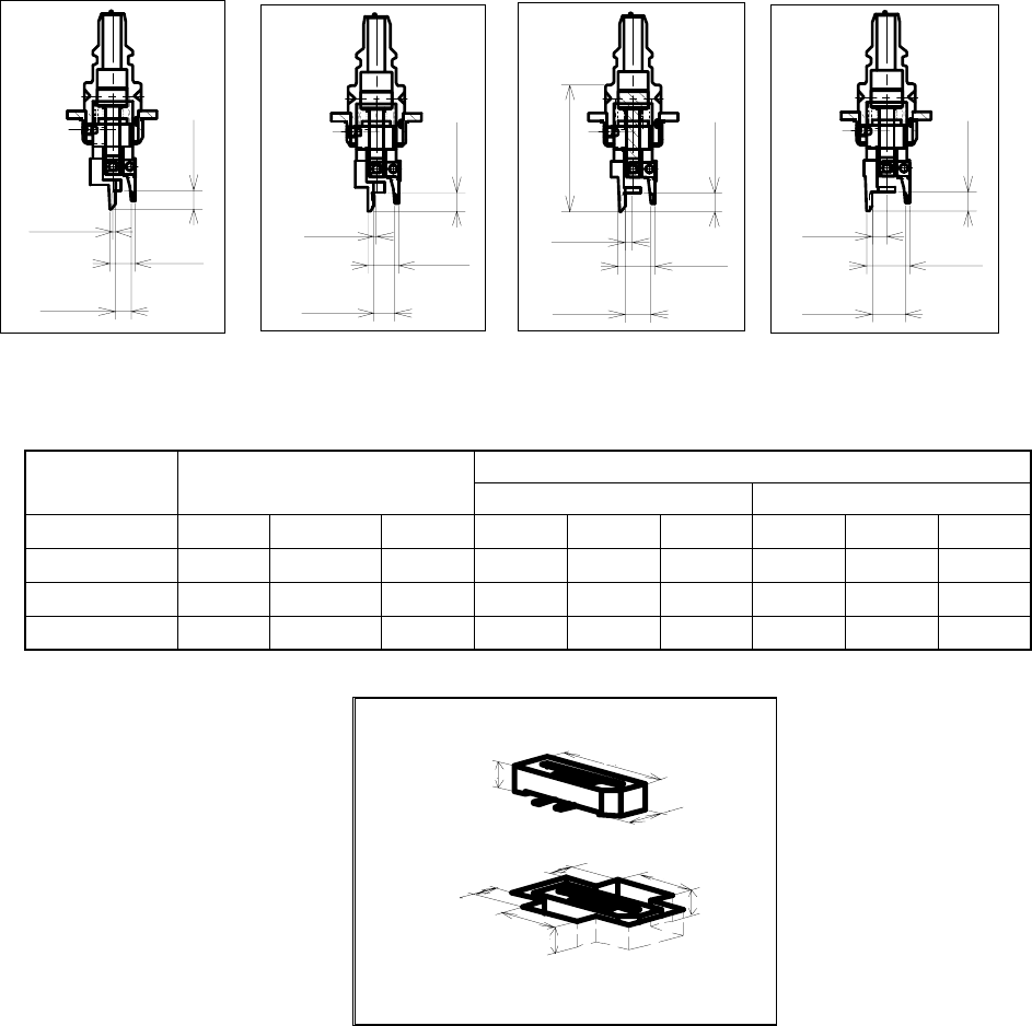
◇ Applicable component and applicable package size
No. 800 nozzle No. 801 nozzle No. 802 nozzle No. 803 nozzle
Figure 12.8.2 Dimensions of nozzles
Table 12.8.1 Applicable components and packaging style
Packaging style (Dimensions of an embossed part) Nozzle
number
Applicable components
Fixed arm side Swing arm side
800 6∼ 0.8∼2.2 5∼ 1.5∼ 5.6∼ 4∼ 3∼ 5.6∼ 2.5∼
801 6∼ 1.8∼3.2 5∼ 1.5∼ 5.6∼ 4∼ 3∼ 5.6∼ 2.5∼
802 6∼ 2.8∼4.2 5∼ 1.5∼ 5.6∼ 4∼ 3∼ 5.6∼ 2.5∼
803 6∼ 3.8∼5.2 5∼ 1.5∼ 5.6∼ 4∼ 3∼ 5.6∼ 2.5∼
H
X
Y
A
D
E
B
F
C
3.8
0.5
5.7
3.5
2.8
-0.5
4.7
3.5
3.5
1.5
4.8
6.7
24
±
0.01
5.8
2.5
7.7
3.5
12 − 13
3. How to Use a Gripper Nozzle
3.1 Load information on a gripper nozzle from a floppy disk on the Machine
Setup menu.
* Once you load information, it is stored on the machine, so you do not have
to perform this operation every time you use the machine.
◇
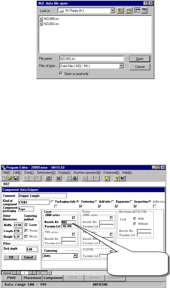
Select the [Read nozzle data] command on the “File” menu invoked from
the Machine setup menu. The following “Nzl. data file open” dialog box
appears. Load the nozzle information file for a gripper nozzle from a
floppy disk.
(See the chapter on the Machine Setup menu for details.)
Figure 12.8.3 “Nzl. data file open” dialog box
3.2 Creating Component data
See the chapter on Component data for details on the operation to be
performed.
◇ Component data creating example
The following example shows how to create Component data that specifies
gripper nozzles to be used.
①
Setting the nozzle number
Figure 12.8.4 Setting the nozzle number
The gripper nozzle
number is from 800
to 899.
12 − 14
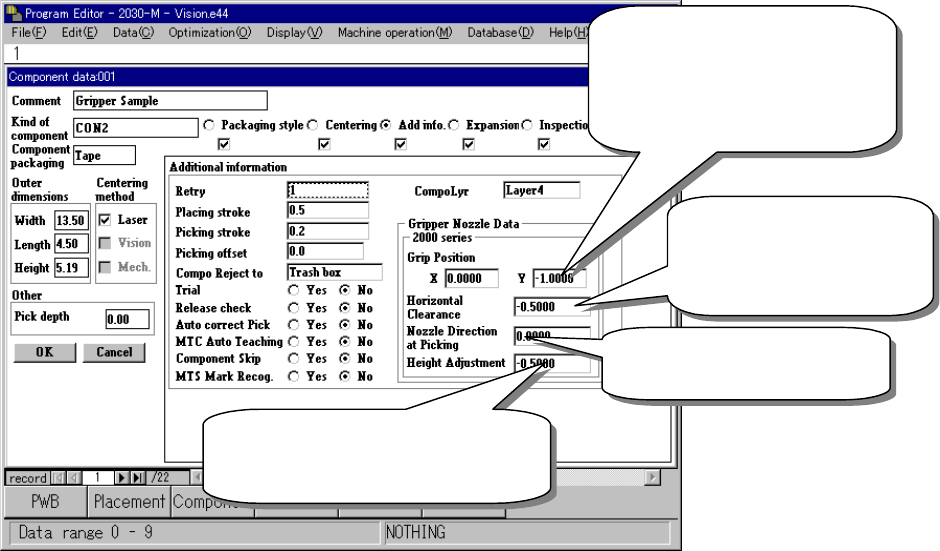
②
Entering information for controlling a component position picked up by a
gripper nozzle
Figure 12.8.5 Setting the gripper control information
③
Laser pos. (position)
Be careful to enter this setting item when you use a gripper nozzle.
Normally, enter the distance from the top of a component to the surface on
which laser beam impinges in the “Laser pos.” field of a nozzle. However,
when you use a gripper nozzle, enter the distance laser is beamed by
regarding the tip of the nozzle that is located at the fixed arm as a reference
position.
Distance between the fixed arm
and the center of a component
Enter half of the width of the
component-molded part.
(Enter a negative value.)
Clearance between the
fixed arm and the
component molded part
(Enter a negative value.)
Specify the angle of a nozzle
(normally set to 0 degrees.)
A griper nozzle has a dumper. To
hold a component horizontally, enter
about – 0.5 mm as a push-in stroke.