KE-2030使用说明书.pdf - 第523页
7 − 29 (3) Product ion oper ation T able 7.2.2.7.3 Placement when set to “Unused” No. Unit Production operation 1 Stops by detected feeder float The X Y speed becomes slower w hen the sensor detects feeder floating while…
7 − 28
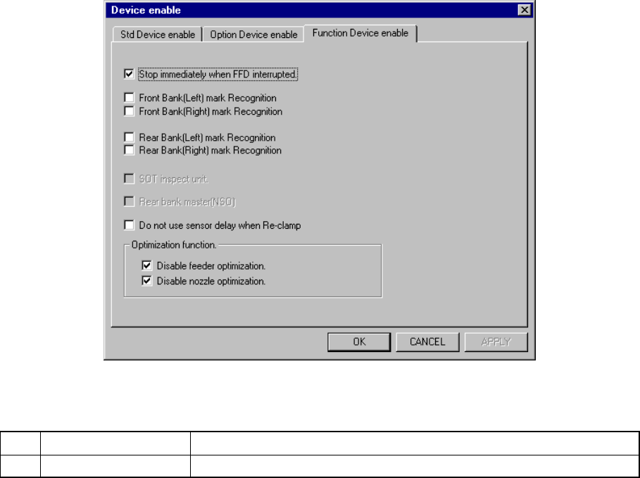
7.2.2.7.3 Function Device enable
A screen appears as shown in Figure 7.2.2.7.3 “Function Device enable setting”
dialog box appears when the [Function Device enable ] tab is selected the “Device
enable” setting dialog box.
Figure 7.2.2.7.3 Function Device enable setting dialog box
(1) Setting items
No. Item Description
1 Function Device enable Function to be used/not used
If the production program requires the functions above to place components
on a board successfully, and you specify them as “unused”, see Table
7.2.2.7.3 which shows whether components are placed actually.
Limitations put on operations of the machine if you check any of check boxes
of the “Optimization function” group are described in Table 7.2.2.10.4.
(2) Setting the unit
− Specify the device unit to be used with the check box.
− Any unit without option setting being made as the MS parameter cannot be
checked.
Zeroing is necessary again when changing the head status from as not to be
used.
◇ Back Master-Bank [Non-stop]
− Specifies the position of the master bank during Non-stop operation.
− You can specify this setting regardless of the PWB transport reference
side.
− The setting of the check box “Alternate” on the “Function enable” tab
invoked from the Operation option dialog box is preferred.

7 − 29
(3) Production operation
Table 7.2.2.7.3 Placement when set to “Unused”
No. Unit Production operation
1 Stops by detected
feeder float
The XY speed becomes slower when the sensor detects feeder floating while
the XY axe are moving.
When the sensor detects feeder floating before the XY axes moves, the
machine asks the operator whether to retry the sensor detection operation.
When the operator selects “Retry”, the sensor reconfirms feeder floating.
When he or she selects “Cancel”, the production is terminated.
2 Bank mark Recognition
(front, rear)
The function is disabled but placement of components is carried out.
3 SOT Inspect Stage You cannot specify the SOT direction check on the tracking menu.
4 Back Master-Bank
[Non-stop]
Places the master bank on the front (“Front” means the front side of the main
unit.).
5 Do not use sensor
delay when Re-clamp
Does not use the setting of the “Delay for PWB conveyor sensor” of the
“PWB conveyor” setup group on the Machine setup menu when the system
clamps a board again.
Table 7.2.2.7.4 Placement operation to be performed if you check any of the
check boxes of the “Optimization function” group
No. Unit Production operation
1 Disable feeder
optimization
The “Pick Data” option displayed on the dialog box that appears when you
execute the [Optimization] command on the “Optimization” menu of the
Program Editor utility is fixed to “Auto assign all data”. You cannot select
any other option.
2 Disable nozzle
optimization
The “Nozzle” option displayed on the dialog box that appears when you
execute the [Optimization] command on the “Optimization” menu of the
Program Editing utility is fixed to “Use permanent nozzle setup from MSL
Setup”. You cannot select any other option.
7 − 30
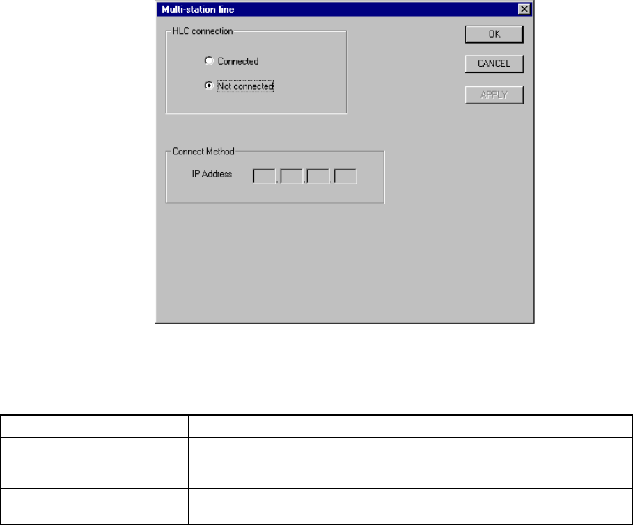
7.2.2.8 Multi-station line
A screen appears as shown in Figure 7.2.2.8.1 “Multi-station line setting dialog box”
when [Multi-station line] is selected from the [Setting Group] menu.
Figure 7.2.2.8.1 Multi-station line setting dialog box
(1) Setting items
No. Item Description
1 HLC connection This command is used to define whether or not this machine is connected to
an HLC in a multi-station line where two or more general purpose placers,
chip placers and bonding machines are connected to the HLC.
2 IP address Since the HLC and each station are to be communicated with each another
via the network, an IP address needs to be defined for each station.
(2) Setting the Multi-station line
① Connection to the HLC
− Using the radio button, define whether or not the machine is to be
connected to the HLC. (Default setting: Not connected)
② Connecting method (IP address)
− Each field of an IP address can be any number from 0 to 255. Two or
more stations cannot have the same IP address. Note that you cannot
set all fields to “0”.
− An IP address is a fixed number for the HLC.
− When “Connected” is selected with the “HLC connection” radio button,
set each field of an IP address to a value from 0 to 255. This dialog
cannot be closed when a number out of that range is set.