KE-2030使用说明书.pdf - 第694页
13 − 5 13.2.2 Piping and joint Check that there is no air leakag e. WA RNING To prevent t he body from injury which can be caused by accidental activation of the machine, turn off the power of the machine before followin…
13 − 4
13.2 Check
13.2.1 Air pressure
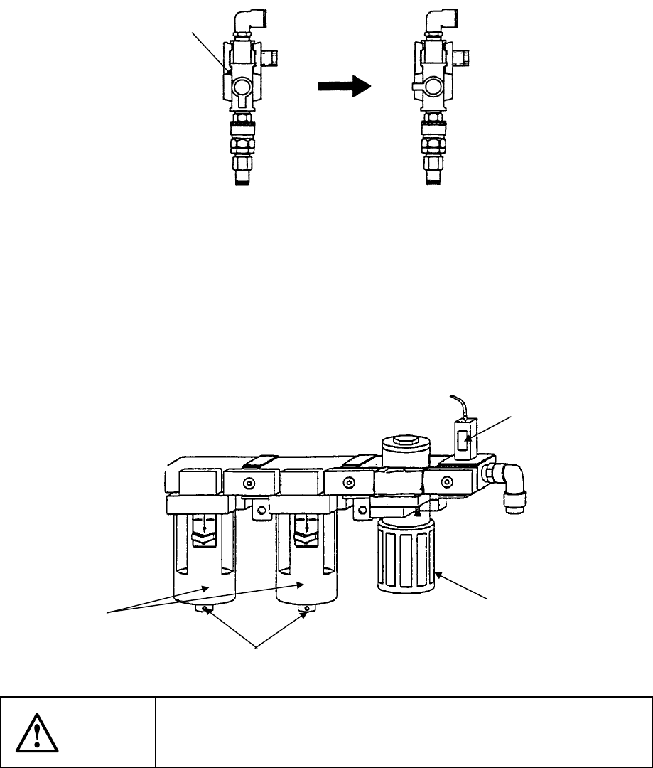
Checking to see if the air pressure is 0.49 Mpa.
How to adjust the air pressure
1) Set the control to the Open position as shown in Figure below.
2) Pull the knob of the regulator ② downward, then rotate it so that the pressure of
the used air can become 0.49 MPa.
3) Peep into the small window ③ located at the center of the pressure switch to
check to see if the pressure is 0.39 MPa (this value is set at the factory).
4) If there is any oil or water in the drain, push the control ④ to drain it out.
WARNING
To prevent the body from injury which can be caused by accidental
activation of the machine, turn off the power of the machine before
following the operation above.
①
CLOSE
OPEN
③
②
④
Drains
13 − 5
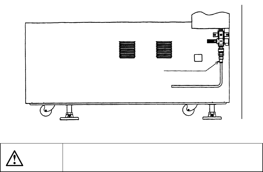
13.2.2 Piping and joint
Check that there is no air leakage.
WARNING
To prevent the body from injury which can be caused by accidental
activation of the machine, turn off the power of the machine before
following the operation above.
13.2.3 Unit air cylinder
Turn on the power of the machine, select the machine setup items, and check that
operation is possible.
Check to see if there is no air leakage.
Front side.
13 − 6
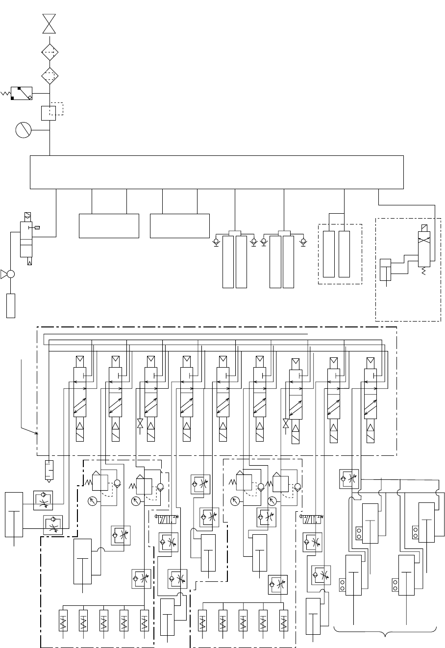
Refer to the following piping diagram.
ø4
ø4
Cell block
ø4
ø6
ø12
ø12
ø8
ø8
ø8
ø8
ø6
ø6
AB
PR
CVS
ø6 ST=30
ø6
ø8
ø6
ø4
ø4
ø4
ø4
ø4
ø4
ø4
ø4
ø4
ø4
ø4
ø4
ø4
ATC L
ATC R
B
A
B
A
B
A
B
A
B
A
B
A
B
A
B
A
B
A
Stopper L
Outer Y pusher L (option)
Outer Y pusher R
Outer X pusher L
Electromagnetic valve
manifold
Outer X pusher R
(Option)
YC check
(Ejector)
(Ejector)
L head unit
R head unit
Connector bracket FL
Connector bracket FR
Connector bracket RL
Connector bracket RR
Drive cylinder 30 RR
Drive cylinder 30 LR Drive cylinder 30 LR
Drive cylinder 30 RF
Drive cylinder 30 LF
(Option)
Overall changer
table F
Overall changer
table R
Manifold
Pressure
gauge
Regulator
Pressure
switch
Mist separator
Filter
Factory-
p
i
p
in
g
(1) Piping diagram (Main body)